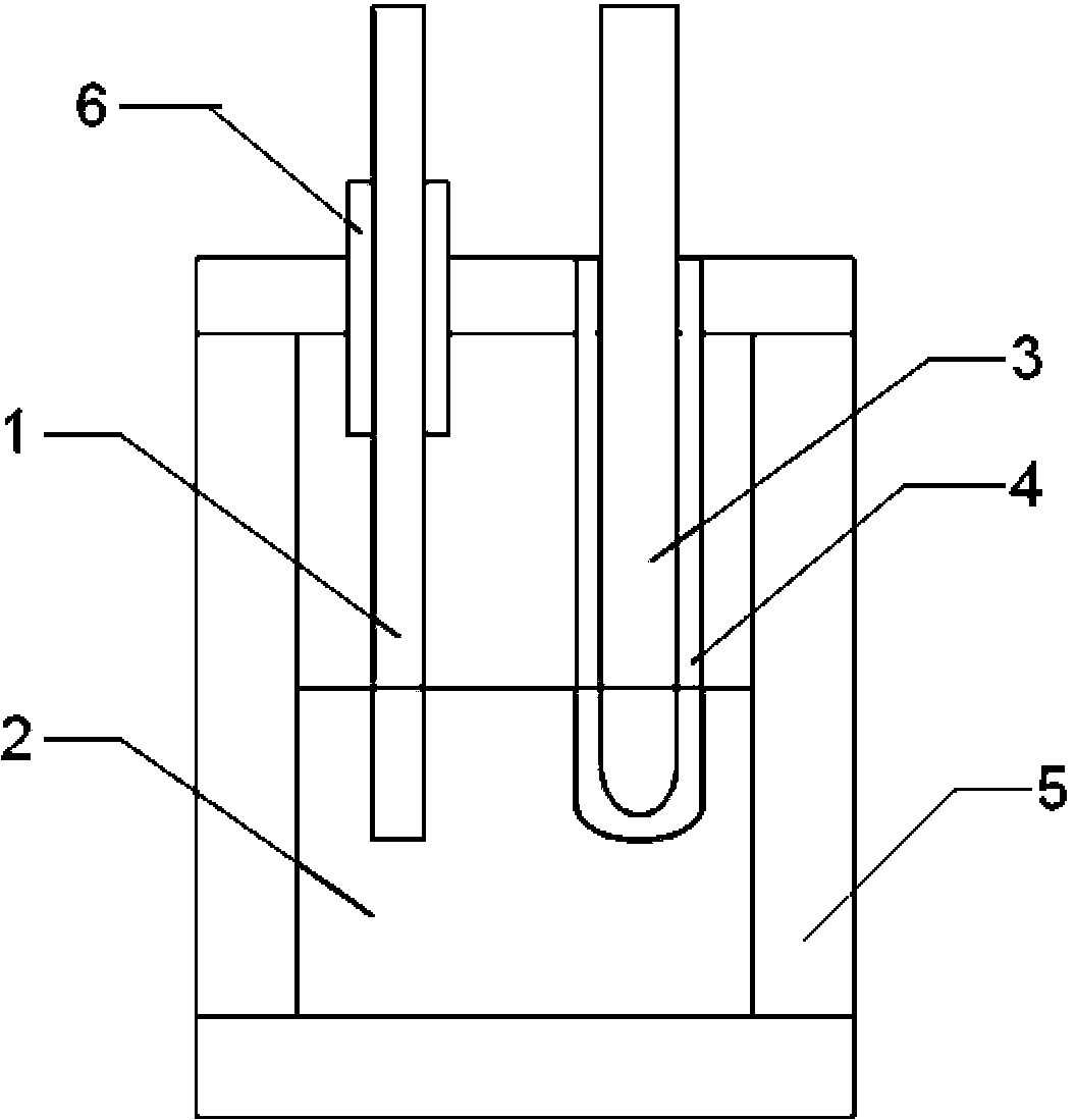
Device and method for purifying rare earth halide
A halide and rare earth technology, which is applied in the field of rare earth material preparation, can solve the problems of complex process, high oxygen content of rare earth halides, and long time consumption, and achieve simple purification process, which is conducive to energy saving and environmental protection and large-scale industrial production , The effect of short electrolysis time
- Summary
- Abstract
- Description
- Claims
- Application Information
AI Technical Summary
Problems solved by technology
Method used
Image
Examples
Embodiment 1
[0033] 1000gLaF 3 Place in a molybdenum crucible, place the graphite anode and cathode tungsten rod coated with solid oxygen-permeable film in the molybdenum crucible, the lower edge of the anode and cathode is 4cm away from the inner plane of the bottom of the crucible, the distance between the cathode and the anode is 7cm, and the solid oxygen-permeable film The material is Y 2 o 3 Stable ZrO 2 ; Connect the entire ventilation pipeline system, and inject high-purity argon to test the airtightness of the pipeline; heat the LaF 3 to 1500°C, forming molten LaF 3 ; Adjust the electrolysis voltage to 2.5V, for molten LaF 3 Electrolysis 2h.
[0034] The purified LaF was measured by dynamic gas adsorption (IGA) 3 O content in medium. The measurement results showed that the purified LaF 3 The O content in the medium is 50ppm. This is because: during the electrolysis process, oxygen ions and graphite rods generate CO or CO 2 while being discharged, thereby achieving de-LaF ...
Embodiment 2
[0036] 1000g CeCl 4 Place in a molybdenum crucible, place the anode and cathode tungsten rods coated with solid oxygen-permeable film in the molybdenum crucible, the lower edge of the anode and cathode is 5cm away from the inner plane of the bottom of the crucible, the distance between the cathode and the anode is 7cm, the material of the solid oxygen-permeable film Use Y 2 o 3 Stable ZrO 2 , the anode is a Li-doped graphite rod; connect the entire ventilation pipeline system, and feed high-purity argon to detect the airtightness of the pipeline; heat CeCl 4 to 590°C, forming molten CeCl 4 ; Adjust the electrolysis voltage to 2.3V, for molten CeCl 4 Electrolysis 4h.
[0037] The purified CeCl was measured by dynamic gas adsorption (IGA) 4 O content in medium. The measurement results show that the CeCl obtained after purification 4 The O content is 40ppm. This is because: during the electrolysis process, some oxygen ions react with active Li to form Li 2 O, some oxyge...
Embodiment 3
[0039] Put 1000g of PrBr in the molybdenum crucible, place the anode and cathode tungsten rod coated with solid oxygen permeable film in the molybdenum crucible, the lower edge of the anode and cathode is 4.5cm away from the inner plane of the bottom of the crucible, the distance between the cathode and the anode is 7cm, solid Oxygen permeable membrane material adopts Y 2 o 3 Stable ZrO 2 , the anode is a graphite rod doped with Na; connect the entire ventilation pipeline system, and feed high-purity argon to detect the airtightness of the pipeline; heat the PrBr 3 to 700°C, forming molten PrBr 3 ; Adjust the electrolysis voltage to 2.8V, for melting PrBr 3 Electrolysis 1.5h.
[0040] Determination of purified PrBr by dynamic gas adsorption (IGA) 3 O content in medium. The measurement results show that the PrBr obtained after purification 3 The O content is 40ppm. This is because: during the electrolysis process, some oxygen ions react with active Na to form Na 2 O, s...
PUM
| Property | Measurement | Unit |
|---|---|---|
| melting point | aaaaa | aaaaa |
Abstract
Description
Claims
Application Information
 - R&D
- Intellectual Property
- Life Sciences
- Materials
- Tech Scout
- Unparalleled Data Quality
- Higher Quality Content
- 60% Fewer Hallucinations
Browse by: Latest US Patents, China's latest patents, Technical Efficacy Thesaurus, Application Domain, Technology Topic, Popular Technical Reports.
© 2025 PatSnap. All rights reserved.Legal|Privacy policy|Modern Slavery Act Transparency Statement|Sitemap|About US| Contact US: help@patsnap.com

