Micro cooling device of silicon-substrate capillary pump loop

A technology of coolers and capillary pumps, applied in cooling/ventilation/heating transformation, instruments, circuits, etc., can solve problems such as excessive heat generation, uneven heating of microelectronic chips, and increased heat load of microelectronic chips, and achieve reduction Small working medium flow resistance, enhanced heat transfer and temperature control capability, and safe and reliable working performance

Inactive Publication Date: 2013-12-11
JIANGSU UNIV
View PDF5 Cites 11 Cited by
  • Summary
  • Abstract
  • Description
  • Claims
  • Application Information

AI Technical Summary

Problems solved by technology

[0005] In view of the fact that the existing CPL heat pipe heat dissipation technology is difficult to solve the problem that the rapid increase of the working heat load of the microelectronic chip causes excessive heat generation and the uneven heat generation of the microelectronic chip itself will cause local "hot spots" on the surface. The present invention provides a silicon The micro-cooler based on the capillary pump

Method used


Image

  • Micro cooling device of silicon-substrate capillary pump loop
  • Micro cooling device of silicon-substrate capillary pump loop
  • Micro cooling device of silicon-substrate capillary pump loop

Examples


Example Embodiment

[0031] Example 1

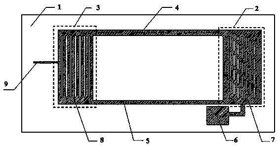
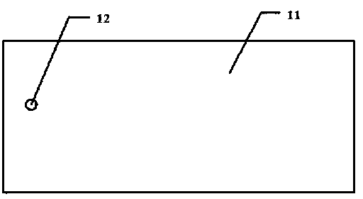
[0032] Such as figure 1 , image 3 As shown, a silicon-based capillary pump circuit micro-cooler is formed by bonding a pair of semiconductor silicon wafers and heat-resistant borosilicate glass wafers 11 and can be directly integrated with semiconductor microelectronic chips. The surface of silicon wafer 1 in contact with the borosilicate glass wafer is etched with evaporator 2, condenser 3, vapor phase channel 4, liquid phase channel 5, liquid storage chamber 6 and vacuum / liquid injection channel 9; evaporator 2 The condenser 3 is connected by the vapor phase channel 4 and the liquid phase channel 5 to form a closed loop; the evaporator 2 includes micro channels inside, and the condenser 3 includes condensation micro channels 8; the condensation micro channels 8 are etched along the condensate flow direction The borosilicate glass sheet 11 is formed with a vacuum / liquid injection hole 12; the vacuum / liquid injection hole 12 is connected to the condenser and...

Example Embodiment

[0036] Example 2

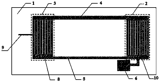
[0037] Such as figure 2 , image 3 As shown, the same as the embodiment 1, the difference is that the evaporator 2 of the capillary pump circuit is not the micro-rib array capillary structure 7 described in the embodiment 1, but an evaporation microchannel 10 similar to the condenser 3.

Example Embodiment

[0038] Example 3

[0039] The same as Example 1 and Example 2, the difference is that the cross-sectional dimensions of the vapor phase channel 4 and the liquid phase channel 5 in the silicon-based capillary pump loop micro cooler change linearly along the channel direction, and the vapor phase channel 4 is from the evaporator 2 It increases linearly toward the condenser 3, while the change of the liquid phase channel 5 is just the opposite. The width of the vapor phase channel increased from 600μm to 1200μm, and the corresponding channel hydraulic diameter increased from 300μm to 342.9μm; the cross-sectional area of ​​the liquid phase channel 5 decreased linearly from the evaporator 2 to the condenser 3, and the channel width decreased from 700μm. To 300μm, the corresponding channel hydraulic diameter is reduced from 311.1μm to 240μm. After the above adjustments, it is beneficial to enhance the spontaneous movement effect of the cooling medium in the vapor phase channel 4 and ...


PUM


Abstract

The invention discloses a micro cooling device of a silicon-substrate capillary pump loop and belongs to the temperature-control field of microelectronic chips. The micro cooling device of the silicon-substrate capillary pump loop is formed by bonding a pair of semi-conductor silicon wafers and a heat-resistant boron silicic acid glass piece. An evaporator, a condenser, a vapor phase channel, a liquid phase channel, a liquid storing cavity and a pumping or liquid filling channel are formed in the contact surface between the silicon wafers and the heat-resistant boron silicic acid glass piece in an etching mode. The evaporator and the condenser are connected through the vapor phase channel and the liquid phase channel to form a closed circuit. The evaporator comprises a micro conduit. The condenser comprises a condensing micro channel. A pumping or liquid filling hole is machined in the silicic acid glass piece. The liquid storing cavity is connected with the evaporator. The micro cooling device of the silicon-substrate silicon substrate loop can be directly integrated with a semi-conductor microelectronic chip so as to effectively reduce the temperature and the temperature gradient of the chip. The problems of hot spots caused by local high heat flow are reduced and relieved. Safe and reliable operation of the chip is ensured.

Description

technical field [0001] The invention relates to a high-efficiency micro-cooling device, in particular to a silicon-based capillary pump circuit micro-cooler, which belongs to the field of temperature control of microelectronic chips. Background technique [0002] With the rapid development of the semiconductor information and communication industry, the high integration and miniaturization of various related products and equipment has become an important development trend, which leads to a rapid increase in the heat load of microelectronic chips and the problem of excessive heat generation. Seriously affect the reliability of its work and even the entire system. At the same time, the uneven heating of the microelectronic chip itself will generate "hot spots" on the surface (the heating intensity can exceed 10 7 W / m 2 ), its existence is considered to be the key reason causing the chip "thermal runaway" and threatening system security. In view of the small cooling space an...

Claims


Application Information

Patent Timeline
IPC IPC(8): H05K7/20H01L23/367H01L23/42G06F1/20
Inventor 屈健王谦何志霞王颖泽
Owner JIANGSU UNIV
Why Eureka
Try Eureka