Bearing device and hydraulic machine

A bearing device and hydraulic machinery technology, which is applied in the field of hydraulic machinery and bearing devices, can solve problems such as bearing load capacity, bearing temperature and bearing performance adverse effects

Active Publication Date: 2013-12-18
KK TOSHIBA
View PDF11 Cites 7 Cited by
  • Summary
  • Abstract
  • Description
  • Claims
  • Application Information

AI Technical Summary

Problems solved by technology

If the deviation of the bearing clearance is large among the guide bearings, it will have an adverse effect on bearing performance such as bearing load capacity and bearing temperature.

Method used


Image

  • Bearing device and hydraulic machine
  • Bearing device and hydraulic machine
  • Bearing device and hydraulic machine

Examples


no. 1 approach )

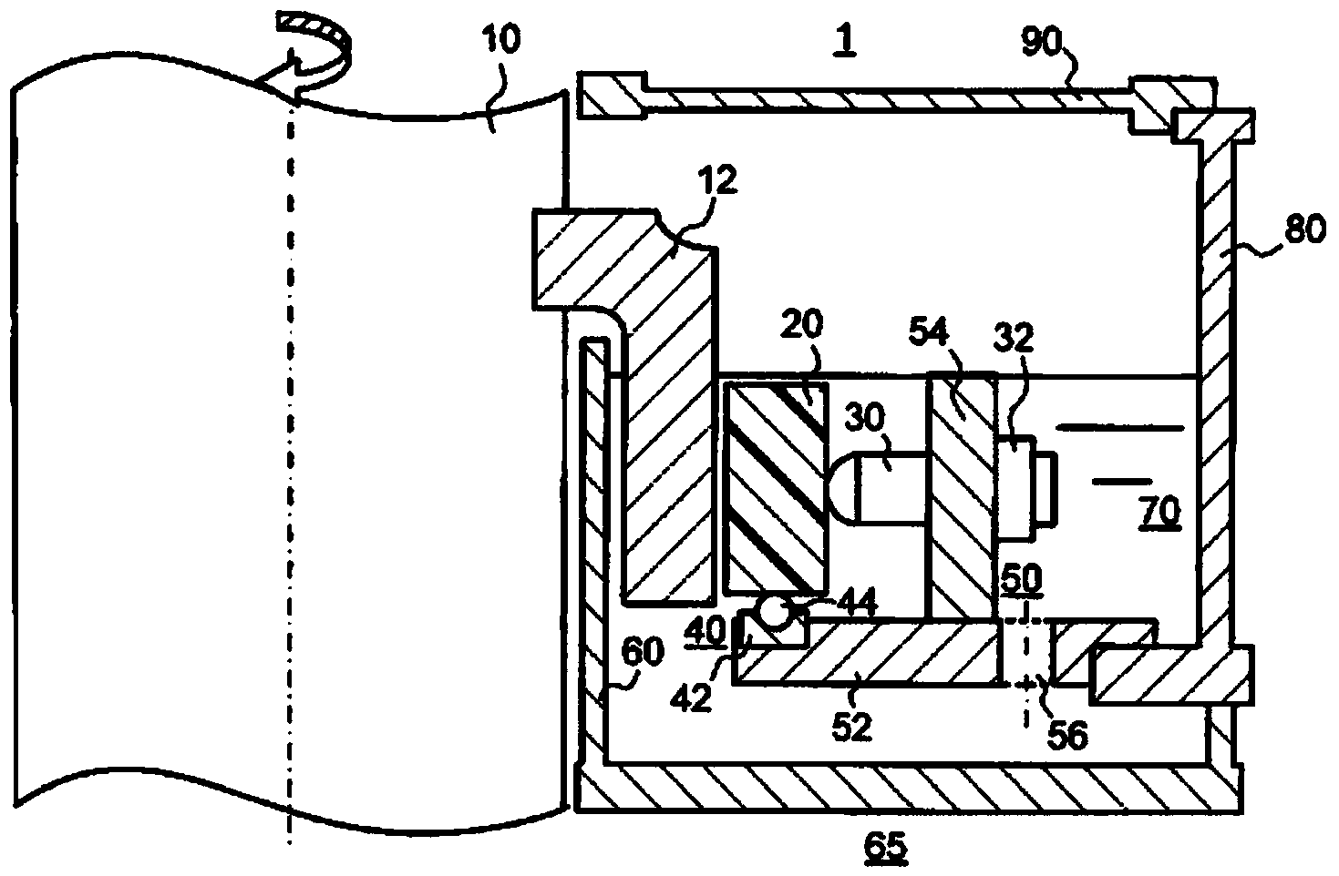
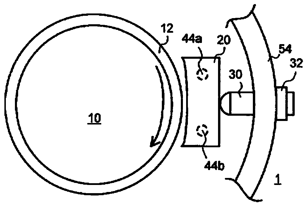
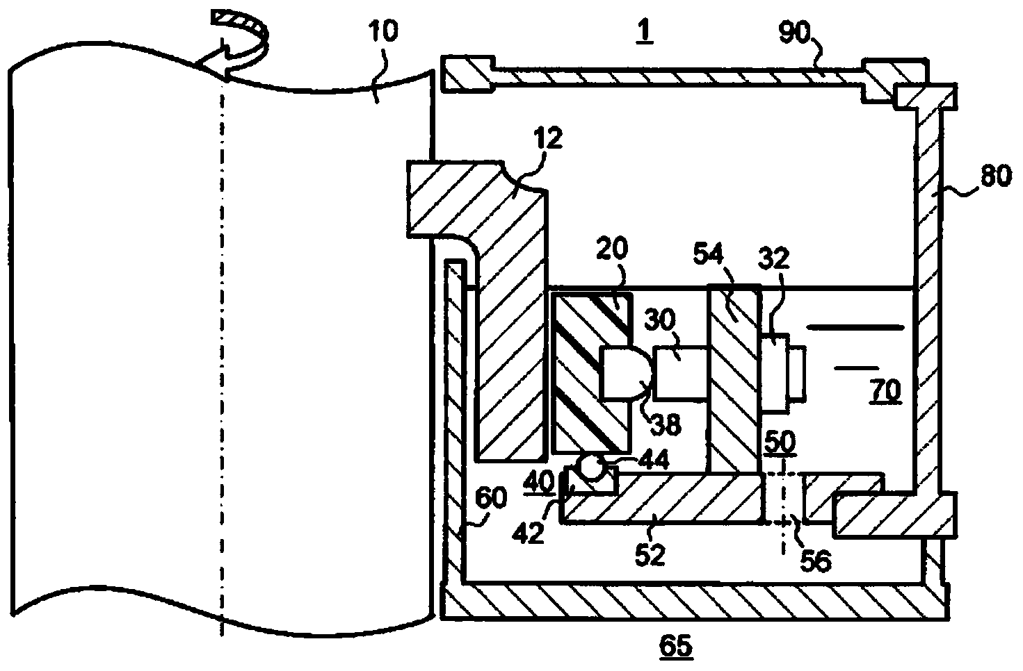
[0083] Hereinafter, embodiments will be described in detail with reference to the drawings. Figure 1A It is a longitudinal sectional view showing the structure of the guide bearing of the first embodiment, Figure 1B It is a plan view showing the structure around the bearing pad in the same guide bearing. Figure 2A , 2B and 2C for denoting Figure 1A Figure showing a modified example of the guide bearing.

[0084] Such as Figure 1AAs shown, a plurality of guide bearings 1 according to the embodiment are arranged along the peripheral surface of a rotating shaft 10 to which a vertical shaft such as a water turbine is connected, for example. The guide bearing 1 is supported at the periphery of the rotating shaft 10 by a bearing stand 80 having a wall surface coaxial with the peripheral surface, and a bearing support stand 50 extending from the wall surface of the bearing stand 80 in the direction of the rotating shaft 10 . A water cylinder 60 is arranged below the guide bear...

no. 2 approach )

[0139] Next, refer to Figure 17 ~ Figure 21 , and the second embodiment will be described in detail. The guide bearing 2 of the second embodiment is configured to actively circulate lubricating water in the guide bearing 1 of the first embodiment. In the following description, common reference numerals are assigned to elements common to those of the first embodiment, and redundant descriptions will be omitted.

[0140] Such as Figure 17 As shown, the guide bearing 2 of this embodiment has a bearing stand 80 having a wall surface coaxial with the peripheral surface and a bearing support stand extending from the wall surface of the bearing stand 80 in the direction of the rotating shaft 10 at the peripheral portion of the rotating shaft 10. 50 and was supported. A water tank 60 is arranged below the guide bearing 2 , and the guide bearing 2 is accommodated in a water tank 65 constituted by the water tank 60 and the bearing stand 80 . A water tank 65 is formed along the per...

specific example 1)

[0160] Such as Figure 22 As shown, in the guide bearing 3 of this embodiment, the lubricating water 70a is tap water containing residual chlorine or chloride ions. The ball bearing 40 is made of austenitic stainless steel. The adjusting bolt 30 and the pin bearing portion (not shown) are made of martensitic stainless steel, and the surface is treated by electroless plating or black anti-rust film treatment. Specifically, the black anti-rust film treatment method is to implement RAYDENT treatment (trade name). The bearing pad base is made of austenitic stainless steel. The shaft skirt 12 is manufactured using martensitic stainless steel and HVOF thermal spraying of a WC—Ni—Cr type ductile thermal spraying material on the surface layer, or is manufactured using austenitic stainless steel. Welded structures such as the bearing support stand 50, the water cylinder 60, the bearing stand 80, and the bearing cover 90 are made of martensitic stainless steel and coated with epoxy r...


PUM


Abstract

Provided are a water-lubricated bearing device that exhibits exceptional bearing performance, is exceptionally corrosion resistant, can prevent abnormal bearing wear, and is adaptable when an adverse event occurs in association with a drop in water level; and a hydraulic machine comprising the bearing device. The bearing device of an embodiment is a bearing device of a hydraulic machine having an upright rotating shaft, the bearing device having a water tank for storing lubricating water, and a bearing pad for supporting a skirt member from the radial direction within the lubricating water, the skirt member being provided to the rotating shaft. The bearing device of the embodiment comprises a first support mechanism for supporting the bearing pad in a slidable manner with respect to the radial direction within the lubricating water, and a second support mechanism for supporting the bearing pad in a slidable manner with respect to the axial bottom side within the lubricating water. In the first support mechanism, either a support surface for supporting the bearing pad or a surface to be supported by the supporting surface in the bearing pad is formed into a convex curved shape. In the second support mechanism, either a support surface for supporting the bearing pad or a surface to be supported by the supporting surface in the bearing pad is formed into a convex curved shape.

Description

technical field [0001] Embodiments of the present invention relate to a bearing device and a hydraulic machine. Background technique [0002] Conventionally, water-lubricated resin bearings have been used in hydraulic machinery such as Kaplan turbines. As this resin, phenolic resin, which is a thermosetting resin, is generally used. However, since the wear resistance against hard foreign matter such as soil and sand in water is not high, clean water after removing foreign matter through a filter is supplied as a lubricant to the bearing sliding surface. In addition, the phenolic resin has a high water absorption rate. Therefore, when machining the inner diameter of the bearing, it is maintained in a state immersed in water in advance, and then the phenolic resin is sufficiently swollen. This is because swelling occurs during operation and the bearing clearance becomes smaller, impairing bearing performance. In addition, an adhesive is used to join the base material and th...

Claims


Application Information

Patent Timeline
Patent Type & Authority Applications(China)
IPC IPC(8): F16C17/02C23C4/04F03B11/06F16C17/14F16C33/12
CPCF03B3/06F03B11/06F05B2250/711F16C17/03F16C33/1025C23C4/06F05B2240/53F05B2260/98F03B11/066F16C2300/34F16C2360/00F16C17/14Y02E10/20F16C17/02C23C4/04F16C33/12Y02T50/60
Inventor 小熊证三上诚龙坦桐木崎康巳筒井政司泷本二三男中川齐年
Owner KK TOSHIBA
Why Eureka
Try Eureka