Unit of recovering flue gas waste heat and dust in reclaimed copper refining

A waste heat recovery device, dust recovery technology, applied in waste heat treatment, lighting and heating equipment, use of liquid separation agent, etc., can solve problems affecting stable production, high energy consumption, environmental pollution, etc., to improve heat recovery rate, protect Spontaneous combustion, environmental protection, and the effect of improving smelting yield

Active Publication Date: 2013-12-25
EAST COPPER CO LTD +1
View PDF7 Cites 0 Cited by
  • Summary
  • Abstract
  • Description
  • Claims
  • Application Information

AI Technical Summary

Problems solved by technology

Dry dust collection and recovery of dust are often used, the process control is unstable, the bag collector is burned out, or the bag is blocked, which leads to shutdown
Seriously affect stable production, and high energy consumption, dust recovery is not complete
Exhaust gas is discharged into the atmosphere, causing environmental pollution

Method used


Image

  • Unit of recovering flue gas waste heat and dust in reclaimed copper refining

Examples


Embodiment 1

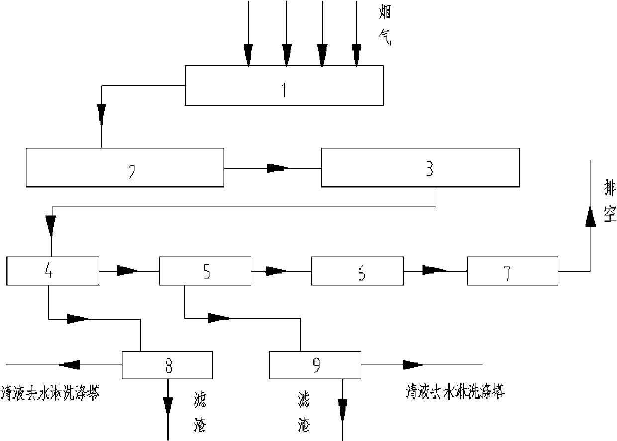
[0062] A recycling device for waste heat and dust in flue gas from secondary copper refining, including a waste heat recovery device and a dust recovery device;

[0063] The waste heat recovery device is composed of a countercurrent heat exchange waste heat boiler A1, a countercurrent heat exchange waste heat boiler B2 and a countercurrent heat exchange waste heat boiler working fluid preheater 3;

[0064] The dust recovery device is composed of a water washing tower 4, a liquid film scrubber 5, a mist catcher 6, an induced draft fan 7, a sedimentation filter A8, and a sedimentation filter B9;

[0065] The waste heat recovery device and the dust recovery device are sequentially connected through pipelines or pipe fittings. The recovery and utilization method of waste heat and dust in the flue gas includes the following steps:

[0066] ①. Primary recovery of waste heat

[0067] The 1350°C flue gas from the secondary copper refining furnace enters the countercurrent heat exchan...

Embodiment 2

[0082] According to the recovery and utilization device of waste heat and dust in the secondary copper refining flue gas of embodiment 1, the difference is:

[0083] The waste heat recovery device used in steps ①, ② and ③ is the countercurrent heat exchange waste heat boiler A1, the countercurrent heat exchange waste heat boiler B2 and the countercurrent heat exchange waste heat boiler working medium preheater 3, and the heat exchange between the flue gas and the boiler working medium is uniform. The three-pipe countercurrent heat exchange method is adopted. The heat exchange device is composed of three straight tubes with different diameters. The flue gas goes through the central tube and the outer ring gap, and the waste heat recovery working fluid goes through the inner ring gap tube. The two flow directions are opposite. Realize countercurrent heat exchange.

[0084] Waste heat recovery rate ≥ 95%. The tail gas discharged meets the emission standard stipulated by the stat...

Embodiment 3

[0086] According to the recovery and utilization device of waste heat and dust in the secondary copper refining flue gas of embodiment 1, the difference is:

[0087] The waste heat recovery device used in step ① is the countercurrent heat exchange waste heat boiler A1. The heat exchange between the flue gas and the boiler waste heat recovery working fluid adopts the double-pipe countercurrent heat exchange method. The heat exchange device consists of several two straight tubes with different diameters The tube set configuration is combined, the flue gas goes through the central tube, and the waste heat recovery working medium goes through the ring gap tube, and the flow directions of the two are opposite to realize countercurrent heat exchange.

[0088] The waste heat recovery device used in steps ② and ③ uses a three-tube countercurrent heat exchange method for the heat exchange between the flue gas and the boiler working fluid in the countercurrent heat exchange waste heat bo...


PUM


Abstract

The invention relates to a unit of recovering flue gas waste heat and dust in reclaimed copper refining and belongs to a method of waste heat utilization and waste gas treatment. The unit comprises a waste heat recovery device and a dust recovery device. The waste heat recovery device comprises a counter flow heat exchange waste heat boiler A (1), a counter flow heat exchange waste heat boiler B (2) and a counter flow heat exchange waste heat boiler medium preheater (3). The dust recovery device comprises a spray scrubbing column (4), a liquid film scrubber (5), an entrainment trap (6), a draught fan (7), a settling filter A (8), and a settling filter B (9). The method includes the steps of primary waste heat recovery, secondary waste heat recovery, tertiary waste heat recovery, spray leaching dust recovery, liquid film dust recovery, entrainment removal, and standard emission of tail gas. The method has the advantages that waste heat recovery is efficient, dust recovery is thorough, recovery cost is low, and waste heat recovery rate is not smaller than 90%.

Description

technical field [0001] The invention relates to a recycling device for waste heat and dust in the flue gas of regenerated copper refining. It belongs to the method of waste heat utilization and waste gas treatment. Background technique [0002] Secondary copper refining is a process in which crude copper and miscellaneous copper are used as raw materials, processed and refined to produce refined copper with a copper content ≥ 99.3%, and then cast into a copper ingot or anode plate. [0003] The operation of recycled copper refining anode furnace is divided into four stages: feeding, oxidation, reduction and casting. Among them, the temperature of the flue gas discharged in the oxidation stage is 1200-1300 °C, and the flue gas contains a large amount of dust and carries metal particles in a semi-molten state; in the reduction stage, heavy oil is used as the reducing agent, and its utilization rate is lower than 30%, and the remaining 70% % With the exhaust gas, the temperat...

Claims


Application Information

Patent Timeline
Patent Type & Authority Applications(China)
IPC IPC(8): F27D17/00C22B7/02B01D47/00B01D53/78
CPCY02P10/25Y02P70/10
Inventor 吕庆淮王京连陈春光王春雨韦子木吕瑞新刘靖卢晓东
Owner EAST COPPER CO LTD
Why Eureka
Try Eureka