Low-loss optical fiber and manufacturing method thereof

A manufacturing method and low-loss technology, applied in cladding optical fiber, manufacturing tools, glass manufacturing equipment, etc., to achieve the effects of reducing interface stress, good control, and reducing internal stress

Active Publication Date: 2013-12-25
FENGHUO COMM SCI & TECH CO LTD +1
View PDF8 Cites 14 Cited by
  • Summary
  • Abstract
  • Description
  • Claims
  • Application Information

AI Technical Summary

Problems solved by technology

The emergence of a station distance of more than 300km or even 400km poses a severe challenge to the traditional ultra-long station distance optical communication system
Due to the different attenuation of various modes transmitted in the optical fiber, during the long-distance mode conversion process, the mode with small attenu

Method used


Image

  • Low-loss optical fiber and manufacturing method thereof
  • Low-loss optical fiber and manufacturing method thereof
  • Low-loss optical fiber and manufacturing method thereof

Examples


Embodiment 1

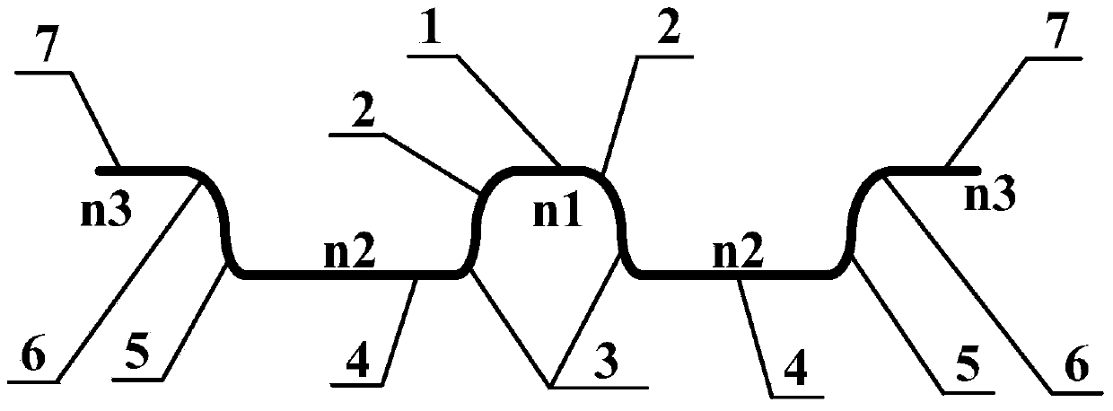
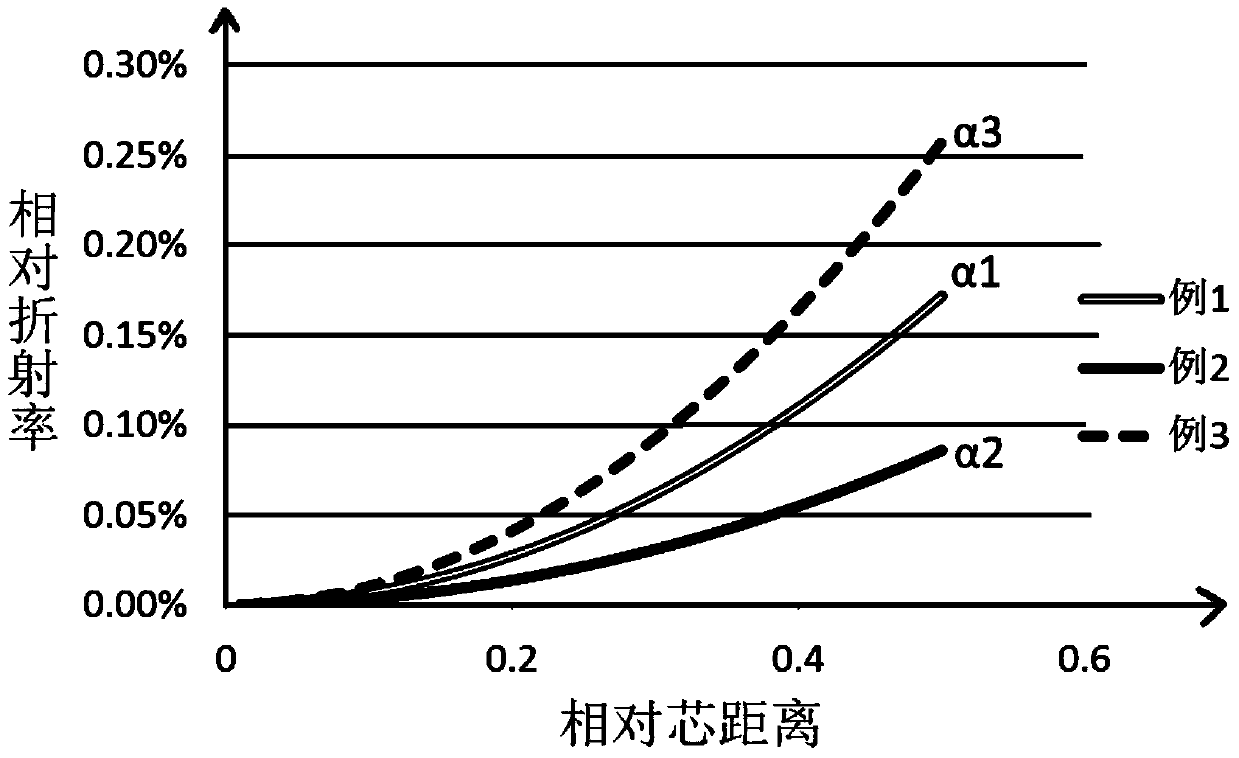
[0041] On the inner wall of a high-purity quartz reaction tube, according to the order from outside to inside, first deposit the cladding interface transition layer 6, then deposit the cladding transition layer 5, then deposit the deep fluorine-doped cladding 4, and then deposit the core cladding interface The transition layer 3 and the core-covered transition layer 2, and finally the core layer 1 is deposited. The specific process is as follows: firstly, the initial value of the base point temperature is set at 900°C, and the cladding interface transition layer 6 is first deposited on the high-purity quartz reaction tube, and its waveguide structure The curve follows the parabolic formula Y=α 1 x 2 , where: Y is the relative refractive index difference, X is the relative distance from the starting point of the refractive index change, α 1 is the stress coefficient, the stress coefficient α in this embodiment 1 The absolute value of remains unchanged, the value is 0.01, and ...

Embodiment 2

[0045] Example 2: The core layer is slightly doped with fluorine

[0046] On the inner wall of a high-purity quartz reaction tube, according to the order from outside to inside, first deposit the cladding interface transition layer 6, then deposit the cladding transition layer 5, then deposit the deep fluorine-doped cladding 4, and then deposit the core cladding interface The transition layer 3 and the core-wrapped transition layer 2, and finally the core layer 1 is deposited. The specific process is as follows: first, the initial value of the base point temperature is 930°C, and the cladding interface transition layer 6 is first deposited on the high-purity quartz reaction tube. The waveguide structure curve Follow the parabolic formula Y=α 2 x 2 +b, where: Y is the relative refractive index difference, X is the relative distance from the starting point of the refractive index change, α 2 is the stress coefficient, b is the change constant of the interface refractive index,...

Embodiment 3

[0050] Example 3: The core layer is slightly doped with fluorine

[0051] On the inner wall of a high-purity quartz reaction tube, according to the order from outside to inside, first deposit the cladding interface transition layer 6, then deposit the cladding transition layer 5, then deposit the deep fluorine-doped cladding 4, and then deposit the core cladding interface The transition layer 3 and the core-wrapped transition layer 2, and finally the core layer 1 is deposited. The specific process is as follows: first, the initial value of the base point temperature is 950°C, and the cladding interface transition layer 6 is first deposited on the high-purity quartz reaction tube. The waveguide structure curve Follow the parabolic formula Y=α 3 x 2 , where: Y is the relative refractive index difference, X is the relative distance from the starting point of the refractive index change, α 3 is the stress coefficient, the stress coefficient α in this embodiment 3 The absolute v...


PUM


Abstract

The invention discloses a low-loss optical fiber and a manufacturing method of the low-loss optical fiber, and relates to the field of optical fibers. The low-loss optical fiber comprises a step change waveguide; the step change waveguide comprises a core layer, a core cladding transition layer, a core cladding interface transition layer, a deep fluorine-doped cladding, a cladding sleeve transition layer, a cladding sleeve interface transition layer and a sleeve layer, wherein the core layer, the core cladding transition layer, the core cladding interface transition layer, the deep fluorine-doped cladding, the cladding sleeve transition layer, the cladding sleeve interface transition layer and the sleeve layer are arranged in sequence from inside to outside; the core layer is made of a pure silicon core slightly doped with fluorine or boron, wherein the relative refringence between the core layer and the pure silicon core is 0-0.1%; the deep fluorine-doped cladding is made of pure silicon dioxide deeply doped with fluorine, wherein the relative refringence between the deep fluorine-doped cladding and the core layer is 0.24%-0.28%; the refractivity in the core cladding transition layer is distributed in a gradient change mode according to a parabola curve, wherein the range of the absolute value of stress coefficients is from 0.005 to 0.015; the base point temperature rises gradually from 900-950 DEG C to 1150-1200 DEG C. The attenuation coefficient of the low-loss optical fiber manufactured according to the manufacturing method can be reduced to less than 0.158 dB/km in a 1550 nm wave band.

Description

technical field [0001] The invention relates to the field of optical fibers, in particular to a low-loss optical fiber and a manufacturing method thereof. Background technique [0002] With the development of optical fiber communication technology towards 100G, 400G ultra-high-speed and large-capacity communication technology, the attenuation requirements for optical fiber are getting higher and higher. In my country, due to the complex terrain and vast territory, optical fiber communication tends to develop towards large capacity and ultra-long station distance. The emergence of a station distance of more than 300km or even 400km poses a serious challenge to the traditional ultra-long station distance optical communication system. In the actual long-distance, large-capacity, high-speed transmission system, the ASE (Amplified Spontaneous Emission, amplified spontaneous emission) noise of the optical amplifier will inevitably damage the system. The influence is more obvious...

Claims


Application Information

Patent Timeline
IPC IPC(8): G02B6/036G02B6/02C03B37/018C03B37/025
CPCC03B2203/22
Inventor 罗文勇李诗愈陈伟柯一礼杜城
Owner FENGHUO COMM SCI & TECH CO LTD
Why Eureka
Try Eureka