Traveling-wave tube clamping rod and manufacturing method thereof

A technology for clamping rods and traveling wave tubes, which is applied in the manufacture of discharge tubes/lamps, discharge tubes, and cold cathodes. Effects of flexibility, improvement of dispersion characteristics, and improvement of machining accuracy

Inactive Publication Date: 2013-12-25
UNIV OF ELECTRONICS SCI & TECH OF CHINA
View PDF7 Cites 3 Cited by
  • Summary
  • Abstract
  • Description
  • Claims
  • Application Information

AI Technical Summary

Problems solved by technology

Since the ceramic clamping rods are relatively fragile, the slow wave structure is easy to break due to uneven force during assembly, resulting in a lot of material waste
If the beryllium oxide ceramic material is used, the beryllium oxide powder produced when it breaks is a highly toxic material, which can easily cause environmental pollution
In addition, when the traveling wave tube works in an environment of high temperature and severe vibration, the ceramic clamping rod is likely to break into several parts, thereby reducing the performance of the traveling wave tube and shortening its life

Method used


Image

  • Traveling-wave tube clamping rod and manufacturing method thereof
  • Traveling-wave tube clamping rod and manufacturing method thereof
  • Traveling-wave tube clamping rod and manufacturing method thereof

Examples


preparation example Construction

[0030] According to one aspect of the present invention, a method for preparing a traveling wave tube ceramic clamping rod is disclosed, comprising the following steps:

[0031] A metal inner core and a ceramic material are selected, and the linear expansion coefficient of the metal inner core is the same or similar to that of the ceramic material;

[0032] First, a layer of metal or alloy layer is plated on the outer surface of the metal inner core, such as one of nickel, copper, silver-copper alloy, gold-copper alloy, germanium-copper alloy, etc., and then on the outer surface of the metal or alloy layer A layer of active metal such as titanium, zirconium, tantalum and niobium is coated on the surface.

[0033] Fixing the metal inner core whose outer surface is coated with a metal layer in the mold for pressing the ceramic clamping rod;

[0034] Fill the mold for pressing the ceramic clamping rod with ceramic material, and start the pressing of the ceramic clamping rod, the...
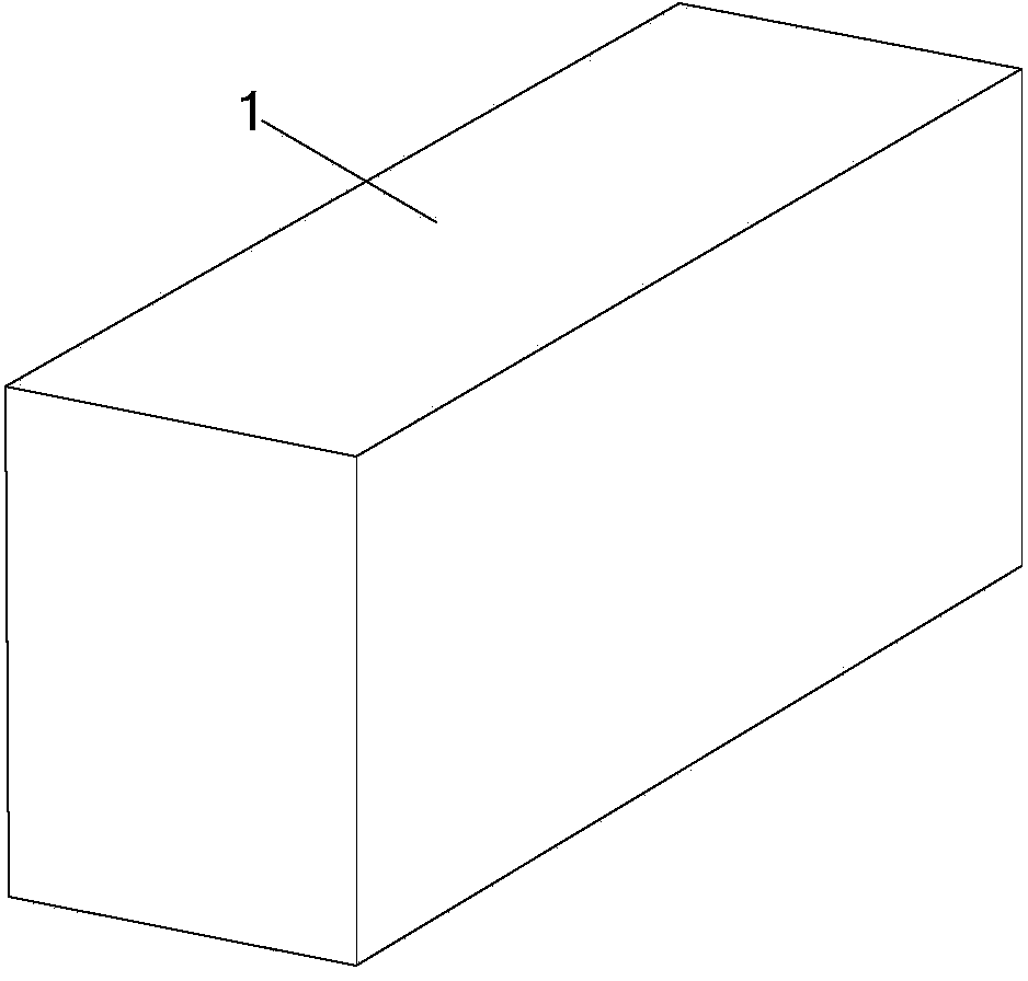
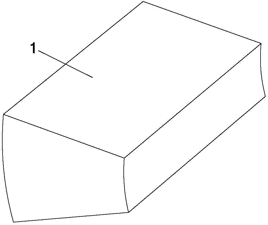
Embodiment 1

[0038] In this embodiment, the cross-section of the ceramic clamping rod and the metal inner core is a rectangular structure, and the metal inner core is located in the center of the ceramic clamping rod as an example, wherein the material of the ceramic clamping rod is beryllium oxide, and the material of the metal inner core is It is the iron-nickel-cobalt magnetic seal alloy 4J34. The long side x short side x length of the rectangular slot is 4 x 5 x 130mm; the long side x short side x length of the rectangular ceramic clamping rod is 4 x 5 x 130mm; the long side x short side of the rectangular metal core cross section x The length is 2×2.5×130mm. The surface of the metal inner core is coated with a layer of 10μm thick nickel layer and titanium layer, and then the metal strip is fixed in the center of the groove, and the groove is filled with beryllium oxide ceramic powder, which is pressed by a normal beryllium oxide after being compacted by a press. The ceramic sintering...
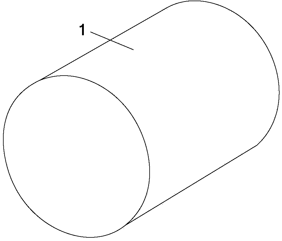
Embodiment 2

[0041]In this embodiment, both the ceramic clamping rod and the metal inner core have a circular cross-section, and the metal inner core is located in the center of the ceramic clamping rod as an example, wherein the material of the ceramic clamping rod is alumina, and the metal inner core The material is iron-nickel-cobalt magnetic seal alloy 4J33. The radius×length of the circular groove is 4×100mm; the radius×length of the circular ceramic clamping rod is 4×100mm; the radius×length of the cross-section of the circular metal core is 2×100mm. Plating a 10μm-thick copper layer and titanium layer on the surface of the metal inner core, then fix the metal strip in the center of the groove, and fill the groove with alumina ceramic powder, press the normal alumina after compaction by a press The ceramic sintering standard is used for sintering, and after sintering, a ceramic clamping rod with a metal inner core for a traveling wave tube designed by the present invention is formed....


PUM

PropertyMeasurementUnit
Poisson's ratioaaaaaaaaaa

Abstract

The invention discloses a traveling-wave tube clamping rod and a manufacturing method thereof. The traveling-wave tube clamping rod comprises a metal inner core and a ceramic material layer located outside the metal inner core, wherein the coefficient of linear expansion of the metal inner core is equal to or close to the coefficient of linear expansion of the ceramic material, and a metal layer or alloy layer which is made of nickel, or copper, or silver-copper alloy, or gold-copper alloy or germanium-copper alloy and a reactive metal layer which is made of titanium, or zirconium, or tantalum or niobium are arranged on the outer surface of the metal inner core. Compared with a conventional ceramic clamping rod, the ceramic clamping rod provided with the metal inner core has the advantage of being better in strength and flexibility, therefore, the traveling-wave tube clamping rod can not be broken easily when used for assembly of a slow wave structure.

Description

technical field [0001] The invention belongs to the technical field of microwave vacuum electronics, and in particular relates to a ceramic clamping rod matched with a slow wave circuit in a traveling wave tube. Background technique [0002] Traveling wave tube is the most important type of microwave and millimeter wave source in the field of vacuum electronics. It has the characteristics of high power, high efficiency, high gain and wide frequency band. It is widely used in microwave and millimeter wave radar, electronic countermeasures, guidance, communication, microwave Remote sensing, micro-blog measurement and other fields. The slow-wave circuit is the core of the TWT, and its performance directly determines the technical level of the TWT. [0003] In the slow wave circuit of the traveling wave tube, such as the helical slow wave system, the double wound helical slow wave system and the ring-rod slow wave system, a large number of ceramic clamping rods are used, and it...

Claims


Application Information

Patent Timeline
Patent Type & Authority Applications(China)
IPC IPC(8): H01J23/00H01J9/00
Inventor 魏彦玉刘鲁伟岳玲娜徐进路志刚赵国庆王战亮黄民智宫玉彬王文祥
Owner UNIV OF ELECTRONICS SCI & TECH OF CHINA
Why Eureka
Try Eureka