
Novel electrolytic bath for aluminum electrolysis and electrolysis technology thereof

An electrolytic cell and electrolytic aluminum technology, applied in the non-ferrous metal smelting industry, can solve the problems of poor corrosion resistance of alloy anodes, high overvoltage of alloy anodes, and high cost of anode materials, and achieve stable oxide film, low power consumption, and difficulty in Effects of Electrolyte Corrosion

Active Publication Date: 2014-01-01
北京润括未来科技有限公司
View PDF8 Cites 21 Cited by
  • Summary
  • Abstract
  • Description
  • Claims
  • Application Information

AI Technical Summary

Problems solved by technology

[0008] The second technical problem to be solved by the present invention is that the alloy anode composed of metal components in the prior art has high overvoltage, the power consumption of the process is large, and the cost of the anode material used is high; in addition, the surface of the alloy anode in the prior art is oxidized The oxide film has low oxidation resistance and is easy to fall off, resulting in poor corrosion resistance of the alloy anode and being continuously consumed, and the corroded or fallen oxide film enters the liquid aluminum and reduces the purity of the final product aluminum; and then proposes a used The anode material has low overvoltage and low price, and the oxide film formed on the surface has strong oxidation resistance, strong stability, and electrolytic corrosion resistance. Electrolytic cell for electrolytic aluminum

Method used


Image

  • Novel electrolytic bath for aluminum electrolysis and electrolysis technology thereof
  • Novel electrolytic bath for aluminum electrolysis and electrolysis technology thereof

Examples


Embodiment 1

[0061] Cathode preparation: 40gTiB 2 Powder, 60g of metal Al powder and 4g of heated and liquefied epoxy resin. After kneading and extrusion molding, the molded product is calcined at 800°C for 6 hours to obtain cathode 1, in which TiB 2 The content of Al is 40wt%, the content of Al is 60wt%; the resistivity of the cathode obtained is 0.073μΩ·m, and the density is 3.42g / cm 3 .

[0062] Anode preparation: Melt 23 parts by weight of Fe metal block, 60 parts by weight of Cu metal block and 0.2 parts by weight of Sn metal block, then mix uniformly under high-speed electromagnetic stirring, and cast quickly at a speed of 20-100°C / s Cooling to obtain anode 1 with uniform texture. The density of the anode is 8.3g / cm 3 , The specific resistance is 62μΩ·cm, and the melting point is 1400°C.

[0063] The electrolyte composition is: NaF, 32%; AlF 3 , 57%; LiF, 3%; KF, 4%; Al 2 O 3 , 4%, of which NaF and aluminum fluoride AlF 3 The molar ratio of is 1.12. The primary crystal temperature of the...

Embodiment 2

[0070] Cathode preparation: 80gTiB 2 Powder, 20g metal Al powder and 8g heated and liquefied phenolic resin were mixed, after kneading and extrusion molding, the molded product was calcined at 1200°C for 2 hours to obtain cathode 2, in which TiB 2 The content of Al is 80wt%, and the content of Al is 20wt%; the resistivity of the cathode obtained is 0.09μΩ·m and the density is 3.9g / cm 3 .

[0071] Anode preparation: 40 parts by weight of Fe metal block, 36 parts by weight of Cu metal block and 5 parts by weight of Sn metal block are melted and mixed uniformly under high-speed electromagnetic stirring, and cast quickly at a speed of 20-100°C / s Cooling to obtain anode 2 with uniform texture. The density of the anode is 7.8g / cm 3 , The specific resistance is 82μΩ·cm, and the melting point is 1369°C.

[0072] The electrolyte composition is: NaF, 38%; AlF 3 , 50%; LiF, 2%; KF, 5%; Al 2 O 3 , 5%, of which NaF and aluminum fluoride AlF 3 The molar ratio is 1.52. The primary crystal temper...

Embodiment 3

[0079] Cathode preparation: 50gTiB 2 Powder, 50g metal Al powder and 6g heated and liquefied epoxy resin. After kneading and extrusion molding, the molded product is calcined at 1000°C for 4 hours to obtain cathode 3, in which TiB 2 The content of Al is 50wt%, and the content of Al is 50wt%; the resistivity of the cathode obtained is 0.09μΩ·m, and the density is 3.65g / cm 3 .

[0080] Anode preparation: 30 parts by weight of Fe metal block, 45 parts by weight of Cu metal block and 3 parts by weight of Sn metal block are melted and mixed uniformly under high-speed electromagnetic stirring, fast casting, at a speed of 20-100°C / s Cooling to obtain anode 3 with uniform texture. The density of the anode is 7.9g / cm 3 , The specific resistance is 86μΩ·cm, and the melting point is 1390°C.

[0081] The electrolyte composition is: NaF, 32%; AlF 3 , 57%; LiF, 3%; KF, 4%; Al 2 O 3 , 4%, of which NaF and aluminum fluoride AlF 3 The molar ratio of is 1.12. The primary crystal temperature of the ...


PUM

PropertyMeasurementUnit
Resistivityaaaaaaaaaa
Densityaaaaaaaaaa
Densityaaaaaaaaaa

Abstract

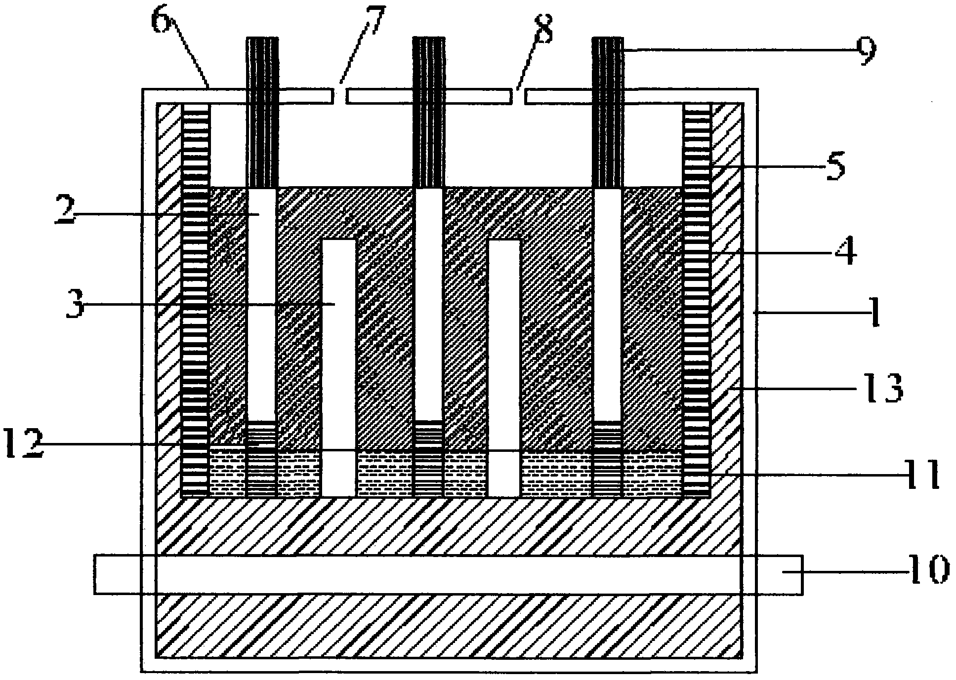
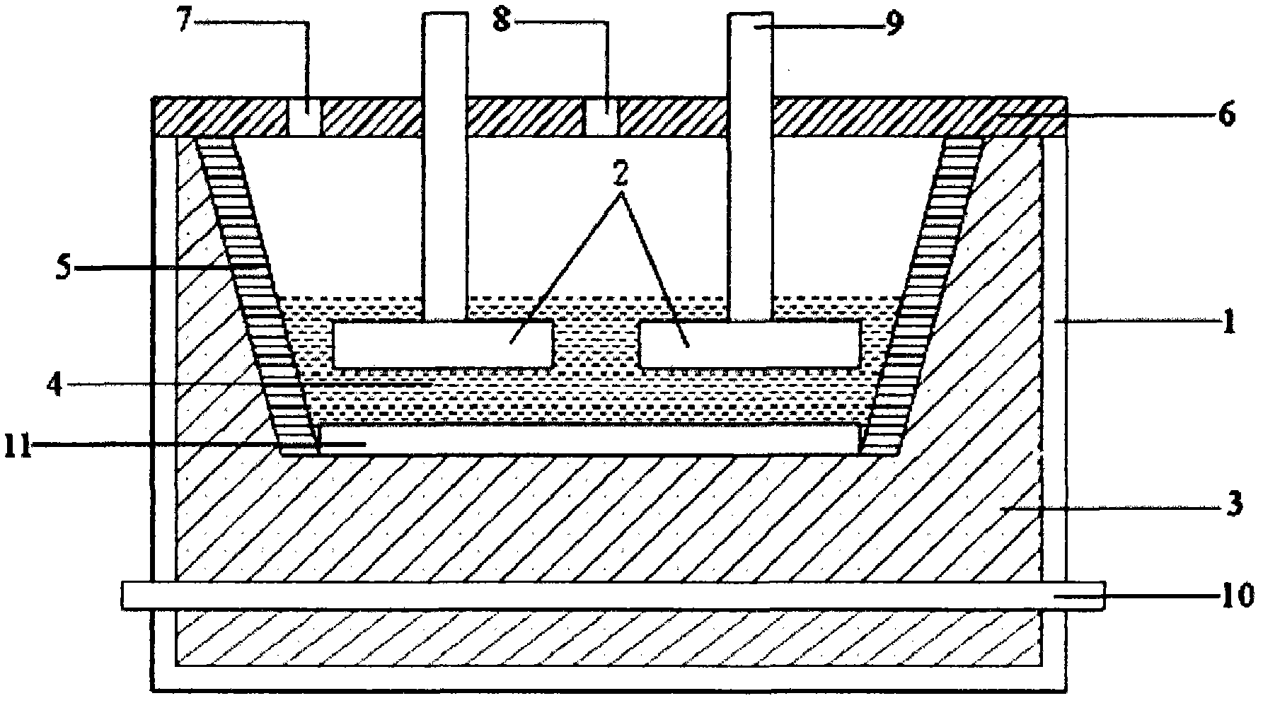
The invention discloses a novel electrolytic bath for aluminum electrolysis and an electrolysis technology thereof. A plurality of anodes and cathodes, which are perpendicular to the bottom of the bath, are parallelly arranged in the bath body, thus a multi-chamber electrolytic bath is formed, and the bath body contains some electrolyte. The electrolytic bath is characterized in that: the cathode is a composite of TiB2 and Al, and has the advantages of low cost, strong wet-ability to liquid aluminum, and no expanding and dropping off in a high-temperature electrolysis environment; the anode comprises following components: Fe, Cu, Ni, and Sn, wherein Fe and Cu is the main components, and the anode has the advantages of low overvoltage, high electric conductivity, low cost, strong oxidation resistant ability, and corrosion resistance; the low-temperature electrolyte is composed of following components in percentage by weight: 30 to 38 wt% of NaF, 49 to 60 wt% of AlF3, 1 to 5 wt% of LiF, 1 to 6 wt% of KF, and 3 to 6 wt% of Al2O3, wherein the mole ratio of NaF to AlF3 is 1.0 to 1.52. The multi-chamber electrolytic bath enlarges the area where electrodes carry out electrolysis reactions, so the yield can be increased by many times compared to that of an industrial single-chamber electrolytic bath if the two kinds of electrolytic baths have the same occupied area.

Description

Technical field [0001] The invention relates to a novel electrolytic cell for electrolytic aluminum and its electrolytic process, belonging to the non-ferrous metal smelting industry. Background technique [0002] Industrial electrolytic aluminum is usually electrolyzed by cryolite-alumina molten salt in a pre-baked carbon anode electrolyzer, that is, cryolite Na 3 AlF 6 The fluoride salt melt is used as a flux, and Al 2 O 3 Dissolve in cryolite, insert the carbon body as the anode vertically into the electrolytic cell, and use the carbon body covered with molten aluminum as the cathode at the bottom of the electrolytic cell. After applying a strong direct current, under the high temperature condition of 940-960℃, Electrochemical reactions are carried out at the two poles of the electrolytic cell, and the produced aluminum liquid product covers the cathode at the bottom of the electrolytic cell. However, the generally used carbon element cathode has poor wettability to the alumin...

Claims


Application Information

Patent Timeline
IPC IPC(8): C25C3/08C25C3/18C25C3/12
Inventor 孙松涛方玉林
Owner 北京润括未来科技有限公司
Learn More