Air negative electrode for microbial fuel cell and preparation method for air negative electrode

A fuel cell and air cathode technology, applied in battery electrodes, electrical components, circuits, etc., to achieve continuous and stable output, low density, and shortened distances

Active Publication Date: 2014-01-01
WUHAN UNIV
View PDF17 Cites 12 Cited by
  • Summary
  • Abstract
  • Description
  • Claims
  • Application Information

AI Technical Summary

Problems solved by technology

[0004]1. The catalytic layer of all microbial air cathodes directly faces the sewage. If the air cathodes cannot resist microbial contamination, the performance of the air cathodes with excellent initial performance will be poor. fall fast
[0005]2. The electrode is immersed in the solution for a long time, and the catalytic layer peels off. Especially in practical engineering applications, the amount of sewage in the anode chamber is large and when it flows in and out There will be a certain amount of hydraulic impact on the catalytic layer, which will cause the materials in the catalytic layer to fall off quickly and cause performance degradation.

Method used


Image

  • Air negative electrode for microbial fuel cell and preparation method for air negative electrode
  • Air negative electrode for microbial fuel cell and preparation method for air negative electrode
  • Air negative electrode for microbial fuel cell and preparation method for air negative electrode

Examples


Embodiment 1

[0031] A microbial fuel cell cathode is composed of a protective layer, a catalytic layer and a diffusion layer.

[0032] The preparation method of the microbial fuel cell air cathode, the specific steps are as follows:

[0033] 1) First place the diffusion layer with a geometric area of ​​4.0cm×4.0cm and a weight of 2.15g on an electrospun polytetrafluoroethylene receiving plate, and the distance between the receiving plate and the nozzle is 15cm.

[0034] 2) Carbon-supported platinum (platinum content 10wt%), Nafion solution and polyacrylic acid (the three are in a mass ratio of 75:15:10) were mixed and ultrasonicated to make an ink.

[0035] 3) Input the ink into the 10mL syringe of the electrospinning device. By controlling the movement trajectory of the needle within the range of 4cm×4cm, apply a DC voltage of 15kV, and the supply rate of the catalyst ink is 2mL / h.

[0036] 4) Spinning, stop when the target catalyst load is reached, and then put into the oven 110 o C dr...

Embodiment 2

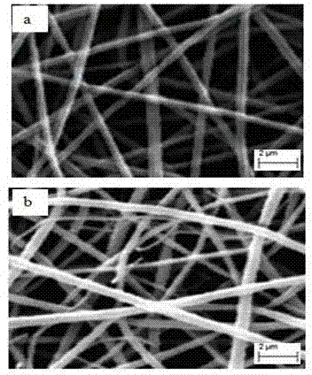
[0043] A microbial fuel cell cathode is composed of a protective layer, a catalytic layer and a diffusion layer. The specific implementation steps are basically the same as in Example 1, except that the protective layer is made of polysulfone organic polymer material and has no antibacterial functional material. image 3 a is the SEM image of the protective layer obtained after Example 2. The pore size ranges from 220nm to 3100nm, with an average of 720nm, the fiber diameter ranges from 250nm to 870nm, with an average of 460nm, the porosity is 91%, and the average thickness of the protective layer is 8μm. The test conditions are basically the same as in Example 1, except that the washing frequency is once every 30 minutes. image 3 b is the SEM image of the surface protective layer of the microbial fuel cell using the air cathode of Example 2 after running for one month, confirming that the polysulfone non-antibacterial material protective layer can prevent microbial contamina...

Embodiment 3

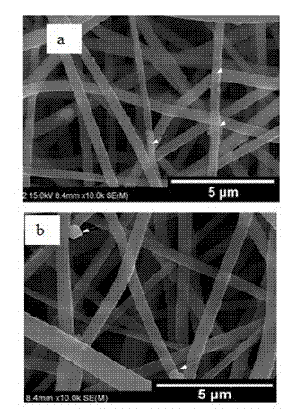
[0046] A microbial fuel cell cathode is composed of a protective layer, a catalytic layer and a diffusion layer. The specific implementation steps are basically the same as in Example 1, except that the protective layer uses a quaternized polysulfone organic polymer material (anion exchange material) and No antibacterial functional materials. Figure 4 a is the SEM image of the protective layer obtained after Example 3. The pore size ranges from 400nm to 6700nm, with an average of 1800nm, the fiber diameter ranges from 340nm to 910nm, with an average of 440nm, the porosity is 81%, and the average thickness of the protective layer is 13μm. The test conditions are basically the same as in Example 1, except that the washing frequency is once every 30 minutes. Figure 4 B is the SEM image of the surface protective layer of the microbial fuel cell that adopts the air cathode of embodiment 2 after running for 1 month, confirms that the quaternized polysulfone anion exchange materia...


PUM

PropertyMeasurementUnit
sizeaaaaaaaaaa
diameteraaaaaaaaaa
sizeaaaaaaaaaa

Abstract

The invention provides an air negative electrode for a microbial fuel cell. The air negative electrode is formed by combining a protective layer, a catalytic layer and a diffusion layer, wherein the protective layer has a porous nano-fiber structure, and is prepared from an inert high polymer material or a high polymer material with ionic conduction capability by using an electrospinning technology; the porous nano-fiber structure has a pore size of 50 to 10000nm and porosity of 50 to 90 percent; the protective layer is 50nm to 1mm thick. According to the air negative electrode, the size and distribution of pores of the protective layer can be controlled to enable ions and water to freely penetrate through the protective layer and disable microbes to penetrate through the protective layer; the protective layer also has a function of fixing the catalytic layer, hydraulic shearing force can be used for removing the microbes attached to the surface of the air negative electrode in a stirring or external circulation pump way in a positive electrode chamber during the running of the microbial fuel cell, and solution ionic conduction is promoted to keep pH in the vicinity of a positive electrode and the negative electrode neutral; a spinning technology is used for electrode preparation, and a process is simple, high in reproducibility and favorable for the broadening of electrode preparation.

Description

[0001] technical field [0002] The invention relates to an air cathode of a microbial fuel cell and a preparation method thereof, belonging to the technical field of fuel cells. Background technique [0003] A microbial fuel cell is an electrochemical device that converts biomass into electrical energy. Its fuel comes from a wide variety of sources and can be utilized without treatment. Using sewage as fuel can also achieve the effect of synchronous treatment of sewage. The air cathode is where the oxygen reduction reaction takes place, and the oxygen reduction reaction is the acceptor for the release of electrons from the anode reaction. The air cathode uses cheap and easy-to-obtain air as a raw material, the battery structure is simple, and the operating cost is low, so it is easy to popularize and use. The preparation method of the air cathode has been extensively studied, such as the Chinese patent "Microbiological fuel cell for recovering electric energy from was...

Claims


Application Information

Patent Timeline
Patent Type & Authority Applications(China)
IPC IPC(8): H01M4/86H01M4/90H01M4/88
CPCY02E60/50H01M4/8605H01M4/8657H01M4/8853H01M4/8882
Inventor 王旭黄种买
Owner WUHAN UNIV
Why Eureka
Try Eureka