Biomass burning device for butt-jointed boilers, heat exchangers and heat supply systems

A technology for heat exchangers and heating systems, applied in the combustion, combustion methods, combustion equipment and other directions of solid fuels, can solve the problems of inability to work continuously and stably, combustion efficiency, low fire temperature, easy to block pipes, etc. The number of times to stop the furnace to clear the slag, reduce carbon deposits, and eliminate the effect of coking

Inactive Publication Date: 2014-02-05
黎明 +1
View PDF8 Cites 2 Cited by
  • Summary
  • Abstract
  • Description
  • Claims
  • Application Information

AI Technical Summary

Problems solved by technology

The traditional biomass burner is mainly composed of a falling hopper, a feeding device, a fan and a furnace, but the traditional biomass burner is easy to coke during the combustion process, easy to block the pipeline, accumulate in the lower part of the furnace and block the screen under the furnace, so that It cannot work continuously and stably due to the need to frequently stop the furnace for slag removal and re-ignition
At the same time, the combustion efficiency of biomass pellet fuel in traditional biomass burners is low, and there is still room for improvement in the fire temperature
[0004] Chinese invention application (publication number CN 101737795 A) discloses "Biomass gasification boiler and coupled ...

Method used


Image

  • Biomass burning device for butt-jointed boilers, heat exchangers and heat supply systems
  • Biomass burning device for butt-jointed boilers, heat exchangers and heat supply systems
  • Biomass burning device for butt-jointed boilers, heat exchangers and heat supply systems

Examples


Embodiment 1

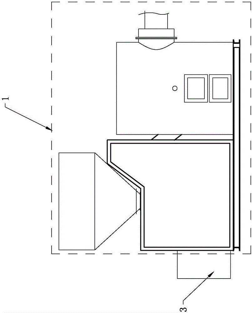
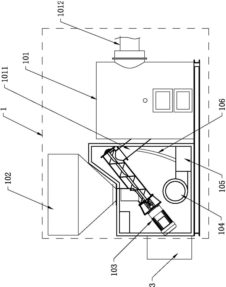
[0044] Biomass combustion devices for docking boilers, heat exchangers, heating systems, such as figure 1As shown, it includes a burner body 1 , a carbonizer for generating the fuel required for combustion of the burner body 1 , and a steam generator 3 . The steam output pipe 301 of the steam generator 3 communicates with the furnace 101 of the burner body 1 . The carbonization machine is equipped with a cracking area and an outlet for discharging cracked gas and tar. The biomass raw material is initially cracked by the carbonization machine and tar is precipitated to obtain biomass fuel. The biomass fuel is sent to the furnace 101 of the burner body 1 for combustion. After the material fuel is burned, the steam generator 3 injects steam into the furnace 101 of the burner body 1 through the steam output pipe 301 . In this embodiment, the burner body 1 is a traditional biomass combustion device for connecting boilers, heat exchangers, and heating systems, and the carbonizer and...

Embodiment 2

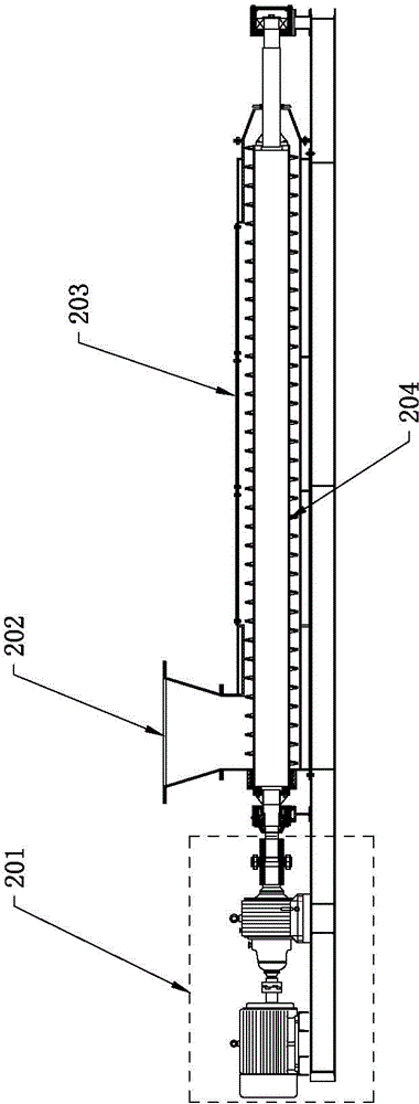
[0050] Such as figure 2 As mentioned above, the difference between the biomass combustion device used for docking boilers, heat exchangers, and heating systems in this embodiment and that in Embodiment 1 is that the carbonization machine in this embodiment is independently developed, and the carbonization machine includes a cracking device , the cracking device comprises a driving device 201, a screw rod 204 and a barrel 203, the driving device 201 is drivingly connected with the screw rod 204, the screw rod 204 is rotatably worn inside the barrel 203, and the inner wall of the barrel 203 is provided with a heating layer and an insulating layer , the insulation layer is arranged between the inner wall of the barrel 203 and the heating layer, a cracking zone is formed between the screw rod 204 and the heating layer, and the cracking zone discharges cracked gas and tar through the discharge port of the cracking device. The barrel 203 of the cracking device in this embodiment is...

Embodiment 3

[0054] The biomass combustion device used for docking boilers, heat exchangers, and heating systems of this embodiment is based on Embodiment 2. The carbonization machine of this embodiment also includes a feeding device. The feeding device includes a feeding hopper, a second Two drive devices, a second barrel and a second screw, the second drive is connected to one end of the second screw, the other end of the second screw is rotatably inserted inside the second barrel, the feed hopper is connected to the second screw The feed end of two barrels communicates, and the discharge end of the second barrel communicates with the cracking zone of cracking device; Below the screw 204 of the device. In this embodiment, since the feeding device is provided with a feeding hopper, the barrel 203 of the cracking device is no longer set into the hopper 202 .

[0055] In order to ensure that the pyrolysis device is in an anoxic and airtight state, the feeding device of this embodiment also...


PUM


Abstract

The invention discloses a biomass burning device for butt-jointed boilers, heat exchangers and heat supply systems. The biomass burning device comprises a burner body, a carbonizing machine and a vapor generator, wherein the carbonizing machine is used for producing fuel required by burning of the burner body; and a vapor output pipe of the vapor generator is communicated with a burning chamber of the burner body. Tar is separated out of raw biomass materials through preliminary cracking by the carbonizing machine, so that the obtained biomass fuel is low in tar content, and the phenomenon of coking inside the burning chamber during burning is effectively avoided. Meanwhile, water vapor is used for supporting burning, so that coking elimination can be facilitated, and the fire temperature of burning flames, the biomass fuel rate and the heat value can be increased. According to the biomass burning device, the carbonizing machine, the vapor generator and the burner body are combined organically, so that the problems that traditional biomass burners are low in burning rate, easy to coke, low in work efficiency, unstable in operation and the like are solved. The biomass burning device can be used for the butt-jointed boilers, the heat exchangers and the heat supply systems as well as other equipment or systems using open fire for heating, such as large thermal motors and the like.

Description

Technical field [0001] The invention involves the field of burning technology, especially the biomass burning device for connecting boilers, heat exchangers, and heating systems. Background technique [0002] Biomass fuels are mostly processed by stem -shaped crops, mainly corn, wheat rice straw, rice shells, straw, wood, etc., which can come from industry, agriculture, forest and living waste, and have a wide range of sources.The water content of general biomass combustion is less than 10%to 15%, the gray content is less than 1.5%, the sulfur content and chlorine content are less than 0.05%, and the nitrogen content is less than 0.5%. It is an ideal renewable energy.The use of biomass combustion as an important direction of new energy development has attracted more and more attention. [0003] At present, the use of biomass fuel is mainly to make biomass into particles, and then send it into the traditional biomass burning machine to combine and fire to heat the boiler, thermal ...

Claims


Application Information

Patent Timeline
IPC IPC(8): F23B90/06F23L7/00
Inventor 黎明梁万泉
Owner 黎明
Why Eureka
Try Eureka