
Biomass pyrolysis carbonization system equipment

A biomass pyrolysis and system equipment technology, applied in the field of pyrolysis carbonization equipment, can solve the problems of long carbonization time, low efficiency, poor working environment, etc., and achieve the effect of industrialized production, improved working environment, and short carbonization time

Inactive Publication Date: 2014-03-12
SHANGHAI ZHONGKE ANDA ENERGY SAVING PROD TECH
View PDF5 Cites 21 Cited by
  • Summary
  • Abstract
  • Description
  • Claims
  • Application Information

AI Technical Summary

Problems solved by technology

At present, the technical devices in this area are mainly the traditional earthen charcoal furnace and vertical carbonization furnace, which have long carbonization time, low efficiency, high energy consumption, and limited applicable raw materials; There has been a great improvement, but there are also problems of continuous feed production and carbon output
The above existing carbonization technology devices all have technical defects such as inability to continuously feed materials, continuous discharge, difficulty in carbonization, poor operating environment, inability to continue carbonization production and only intermittent operations, etc., resulting in low carbonization production efficiency and restricting biomass carbonization. industrial development

Method used


Image

  • Biomass pyrolysis carbonization system equipment
  • Biomass pyrolysis carbonization system equipment
  • Biomass pyrolysis carbonization system equipment

Examples


specific Embodiment approach 2

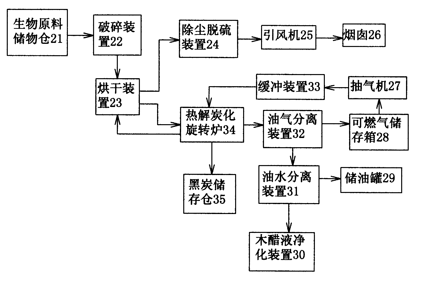
[0034] see figure 2 The difference between this specific embodiment and specific embodiment one is that it also includes an air extractor 27 and a buffer device 33, the combustible gas tank storage box 28 is connected with the air extractor 27, the air extractor 27 is connected with the buffer device 33, and the buffer device 33 is connected with pyrolysis carbonization rotary furnace 34. Other compositions and connections are the same as in the first embodiment.

[0035] The air extractor 27 in this specific embodiment can suck the combustible gas in the combustible gas storage tank 28 into a buffer device 33 such as a compressor, and send it to the pyrolysis and carbonization part through the buffer device 33 to supply heat The decarbonization part generates heat energy for use.

[0036] This specific embodiment can realize the continuous feeding and discharging operation in the process of carbonizing biomass, and ensure the sealing performance between each connecting par...


PUM


Abstract

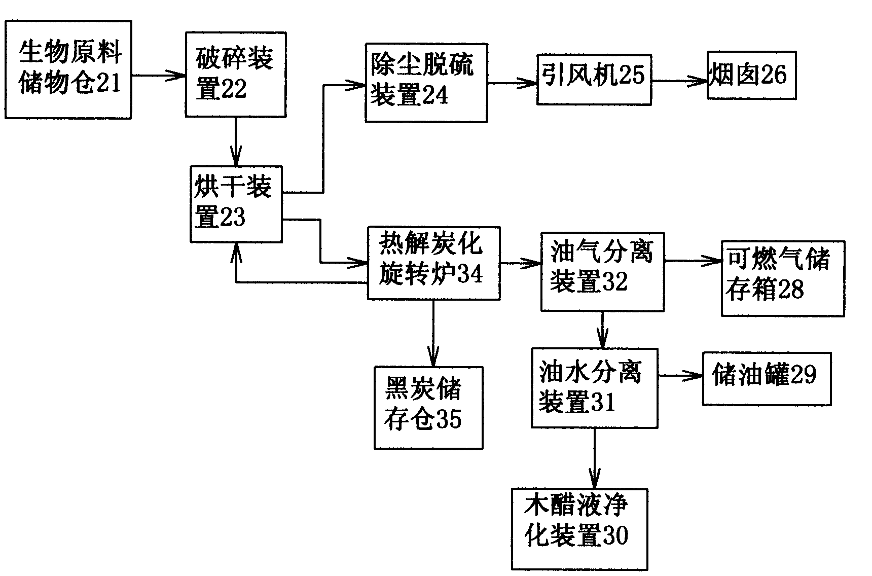
The invention discloses biomass pyrolysis carbonization system equipment and relates to the field of pyrolysis carbonization equipment. The biomass pyrolysis carbonization system equipment is characterized in that a biomass raw material storage tank is connected to a breaker; the breaker is connected to a drying device; the drying device is connected respectively to a dust-removal and desulfurization device and a pyrolysis carbonization rotary furnace; the dust-removal and desulfurization device is connected to an induced draft fan; the induced draft fan is connected to a chimney; the pyrolysis carbonization rotary furnace is connected respectively to an oil-gas separation device and a black carbon storage bin; the oil-gas separation device is connected respectively to a combustible gas bottle storage tank and an oil-water separation device; the oil-water separation device is connected respectively to an oil storage tank and a pyroligneous liquor purifier; and the pyrolysis carbonization rotary furnace is connected to the drying device. The biomass pyrolysis carbonization system equipment realizes high-efficiency carbonization treatment on biomass, continuous feeding and continuous discharge, has a high carbon yield, improves a work environment, realizes industrial production, and has short carbonization time and low energy consumption.

Description

Technical field: [0001] The invention relates to the field of pyrolysis and carbonization equipment, in particular to biomass pyrolysis and carbonization system equipment and a pyrolysis and carbonization rotary furnace used for the pyrolysis and carbonization system equipment. Background technique: [0002] With the depletion of petroleum and other fossil fuels and the global concern about climate change caused by greenhouse gas emissions, development and utilization of renewable energy, improvement of energy efficiency, and realization of energy conservation and emission reduction have become the main theme of world energy development. [0003] Biomass such as crop straw, forestry waste and weeds is a huge renewable resource. As a new energy source, biomass energy has low sulfur, low nitrogen and zero CO 2 characteristics of net emissions. Through the dry distillation pyrolysis carbonization process of biomass, it is converted into industrial products such as high-quality...

Claims


Application Information

Patent Timeline
IPC IPC(8): C10B53/02C10B47/30C10B1/10
CPCY02E50/14Y02E50/10
Inventor 王柏松陈水琴
Owner SHANGHAI ZHONGKE ANDA ENERGY SAVING PROD TECH
Learn More