
Adaptive-optics OCT retina imager using coherence-gated wavefront sensor

A technology of wavefront sensor and adaptive optics, which is applied in the fields of application, medical science, and eye testing equipment, etc., can solve the problems of increasing the appearance size and cost of the instrument, signal loss polarization characteristics, corneal reflection, etc., to reduce the appearance size , reduce requirements, enhance the effect of strength

Active Publication Date: 2014-05-21
INST OF OPTICS & ELECTRONICS - CHINESE ACAD OF SCI
View PDF9 Cites 16 Cited by
  • Summary
  • Abstract
  • Description
  • Claims
  • Application Information

AI Technical Summary

Problems solved by technology

However, these methods have their own shortcomings: (a) lead to more serious aberrations; (b) cause signal loss and depend on the polarization characteristics of the sample; (c) require the imaging optical path and the wavefront detection optical path to be separated, and need to use two light sources
However, in order to avoid the reflected stray light generated at the optical interface, a curved mirror needs to be used between the transverse scanning mechanism and the sample, but this will increase the appearance size and cost of the instrument, and the problem of corneal reflection still exists
There are no related reports on AO-OCT retinal imaging technology using coherent gate wavefront sensing technology

Method used


Image

  • Adaptive-optics OCT retina imager using coherence-gated wavefront sensor
  • Adaptive-optics OCT retina imager using coherence-gated wavefront sensor
  • Adaptive-optics OCT retina imager using coherence-gated wavefront sensor

Examples


Embodiment Construction

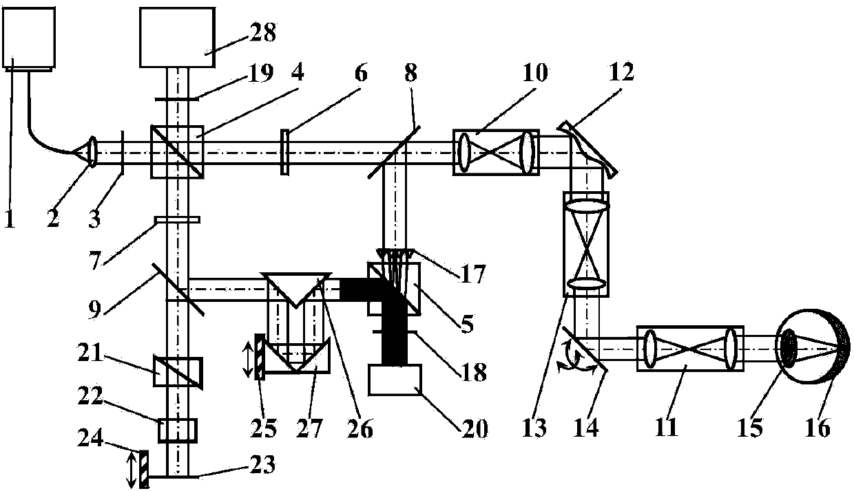
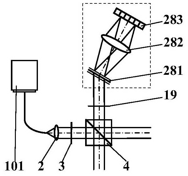
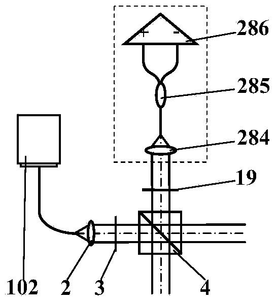
[0027] The system structure of the adaptive optics OCT retinal imager using the coherent gate wavefront sensor proposed by the present invention is as follows: figure 1 As shown, it includes: light source 1, spectral domain OCT light source 101, frequency-swept OCT light source 102, collimator lens 2, polarizer 3, first and second broadband polarization beam splitter prisms 4-5, first and second λ / 4 wave plates 6-7, first and second broadband beam splitters 8-9, first and second beam expanders 10-11, deformable mirror 12, beam reducer 13, two-dimensional scanner 14, human eye refraction System 15, retina 16, microlens array 17, first and second analyzers 18-19, wavefront detector 20, dispersion compensation film 21, water box 22, reference mirror 23, first and second translation stages 24 -25, reflective prism 26, return prism 27, imaging detection module 28, grating 281, imaging lens 282, line array detector 283, coupling lens 284, fiber optic coupler 285, balance detector 2...


PUM


Abstract

An adaptive-optics OCT retina imager using a coherence-gated wavefront sensor comprises a light source, a polarizer, a first broadband polarization light splitting prism, a second broadband polarization light splitting prism, a first lambda / 4 wave plate, a second lambda / 4 wave plate, a first broadband light splitting plate, a second broadband light splitting plate, a deformation mirror, a two-dimensional scanner, a microlens array, a first polarization analyzer, a second polarization analyzer, a wavefront detector, a reference mirror, an imaging detection module, a data acquisition card, a computer, a function generation card, a high-voltage amplifier and the like. By adopting the coherence-gated wavefront sensing technology, the adaptive-optics OCT retina imager collects and corrects wavefront aberrations of an imaged layer in a retina and therefore filters wavefront aberrations produced by other layers and devices in an optical path, and transverse resolution close to the diffraction limit is obtained; besides, the Fourier domain OCT technology comprising spectral domain OCT and sweep frequency OCT is adopted for conducting high-resolution longitudinal tomography of the retina. The adaptive-optics OCT retina imager has the advantages that wavefront detection is insensitive to stray light, the strength of wavefront detection signals can be enhanced, and the external dimension of the adaptive-optics OCT retina imager is reduced.

Description

technical field [0001] The invention relates to a high-resolution imaging device for living human eye retina, in particular to a three-dimensional high-resolution adaptive optical OCT retinal imaging device using coherent gate wavefront sensing technology. Background technique [0002] The introduction of adaptive optics (AO) technology has greatly improved the quality of fundus retinal images obtained by optical coherence tomography (OCT), scanning laser ophthalmoscopy and other technologies. AO technology consists of wavefront sensors (WFS), wavefront correctors, and controllers. Common wavefront sensors include laser ray tracing, Shaker-Hartmann (SH), and pyramid types, all of which can only detect the lateral distribution of wavefront aberrations, but cannot provide aberration information decomposed along the depth. Among them, the most widely used is the Shaker-Hartmann wavefront sensor (SH-WFS), which is composed of a microlens array and a CCD or CMOS two-dimensional ...

Claims


Application Information

Patent Timeline
IPC IPC(8): A61B3/15A61B3/12
Inventor 杨亚良张雨东饶学军
Owner INST OF OPTICS & ELECTRONICS - CHINESE ACAD OF SCI
Learn More