Industrial treatment method and industrial treatment device for oil field waste

A technology for oil field waste and industrial treatment, which is applied in the petroleum industry, the preparation of liquid hydrocarbon mixtures, and earth-moving drilling, etc. The effect of improving vaporization rate and heating rate

Active Publication Date: 2014-07-16
RUIJIE ENVIRONMENTAL PROTECTION TECH CO LTD
View PDF9 Cites 138 Cited by
  • Summary
  • Abstract
  • Description
  • Claims
  • Application Information

AI Technical Summary

Problems solved by technology

These traditional heating and pyrolysis methods have low heating efficiency. To make the pr...

Method used


Image

  • Industrial treatment method and industrial treatment device for oil field waste
  • Industrial treatment method and industrial treatment device for oil field waste
  • Industrial treatment method and industrial treatment device for oil field waste

Examples


Embodiment 1

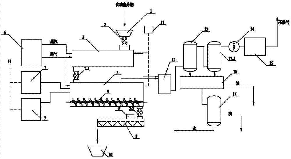
[0060] The industrial treatment device and technological process of the oilfield waste provided by embodiment 1, such as figure 1 shown.

[0061] figure 1 Among them, the feed hopper (1) is connected to the dryer (3) through an air lock (2), and the steam outlet of the steam boiler (6) is connected to the steam inlet of the dryer (3).

[0062] The discharge end of the dryer (3) is connected to the feed end of the microwave heating cavity (4) through an air lock (2-1), and the microwave generator (7) is connected to the microwave heating cavity (4) through a wave guiding device. A paddle conveyor (5) is arranged in the microwave heating cavity (4).

[0063] The gas outlets of the dryer (3) and the microwave heating chamber (4) are connected to the dust remover (12), and the dust remover (12) is connected to the condenser (13) and the condenser (13-1) in turn, and the condenser (13 -1) The gas outlet is connected with the UV high-efficiency gas purifier (15) through the fan (...

Embodiment 2

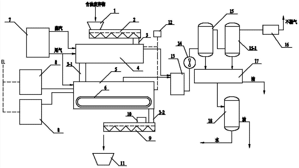
[0070] The industrial treatment device and technological process of the oilfield waste provided by embodiment 2, such as figure 2 shown.

[0071] figure 2 Among them, the feed hopper (1) is connected to the dryer (4) through the feed screw (2) and the rotary feeding device (3), and the steam outlet of the steam boiler (7) is connected to the steam inlet of the dryer (4). The discharge end of the dryer (4) is connected to the feed end of the microwave heating cavity (5) through the rotating unloading device (3-1), and the microwave generator (8) is connected to the microwave heating cavity (5) through a wave guiding device . A feeding conveyor belt (6) is arranged in the microwave heating chamber (5).

[0072] The gas outlets of the dryer (4) and the microwave heating chamber (5) are respectively connected with the dust remover (13), the fan (14), the condenser (15) and the condenser (15-1) in turn, and the condenser (15- 1) The gas outlet is connected to the UV high-effi...

Embodiment 3

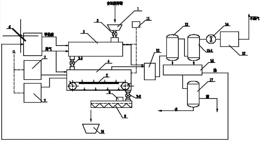
[0078] The industrial treatment device and technological process of the oilfield waste provided by embodiment 3, such as image 3 shown.

[0079] image 3 Among them, the feed hopper (1) is connected to the dryer (3) through an air lock (2), and the heat transfer oil outlet of the heat transfer oil boiler (6) is connected to the heat transfer oil inlet of the dryer (3).

[0080] The discharge end of the dryer (3) is connected to the feed end of the microwave heating cavity (4) through an air lock (2-1), and the microwave generator (7) is connected to the microwave heating cavity (4) through a wave guiding device. A scraper conveyor (5) is arranged in the microwave heating chamber (4).

[0081] The gas outlets of the dryer (3) and the microwave heating chamber (4) are respectively connected to the dust collector (12), the condenser (13) and the condenser (13-1) in turn, and the gas outlet of the condenser (13-1) Connect with activated carbon filter (15) through blower fan (1...


PUM


Abstract

The invention provides an industrial treatment method for oil field waste. The industrial treatment method for oil field waste comprises the following steps: carrying out sampling analysis on the oil field waste, preheating to 80-300 DEG C by using high-temperature steam or conduction oil, then carrying out microwave pyrolysis treatment, controlling pressure at minus 5000 to minus 100 Pa, thus obtaining solid treatment substances and gas, condensing, separating and purifying the gas, and finally recycling so as to obtain water, oil and non-condensable gas. An industrial treatment device for oil field waste comprises a feed hopper, a dryer, a microwave heating cavity, a microwave generator, a heating device and a condensation separation purification device, wherein the feed hopper is connected to the dryer which is connected to the microwave heating cavity, a steam or conduction oil outlet of the heating device is connected to a steam or conduction oil outlet of the dryer; gas outlets of the dryer and the microwave heating cavity are connected to the condensation separation purification device; the microwave generator is connected to the microwave heating cavity. The industrial treatment method and the industrial treatment device have good treatment effects, high utilization rate of energy sources and good economical efficiency.

Description

technical field [0001] The invention relates to the field of oilfield waste treatment, in particular to an industrial treatment method and device for oilfield waste. Background technique [0002] Oilfield waste usually refers to cuttings produced during drilling, water-based mud and oil-based mud, oily sludge and sediment produced during oil production and oil well operations, crude oil-contaminated soil, and crude oil during storage in storage tanks. Tank bottom sediment, etc. In addition to certain petroleum substances, oilfield waste also contains a large amount of benzene series, phenols, anthracene, pyrene and other toxic substances, salts and heavy metals such as copper, zinc, chromium and mercury. These oilfield wastes are not easy to deal with. It takes hundreds of years to completely decompose under natural conditions. Not only does it directly occupy land and space, but it also seriously pollutes air, soil and groundwater, restricting the production and developmen...

Claims


Application Information

Patent Timeline
IPC IPC(8): C10B53/00C10G1/00
CPCC10B19/00C10B53/00C10G1/02C10G1/10E21B21/066
Inventor 陈开军胡天勇梁仁刚何茂金闫亚丽林慧丽
Owner RUIJIE ENVIRONMENTAL PROTECTION TECH CO LTD
Why Eureka
Try Eureka