Copper foil for printed circuit

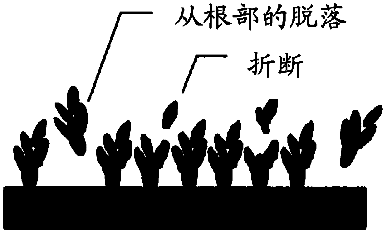
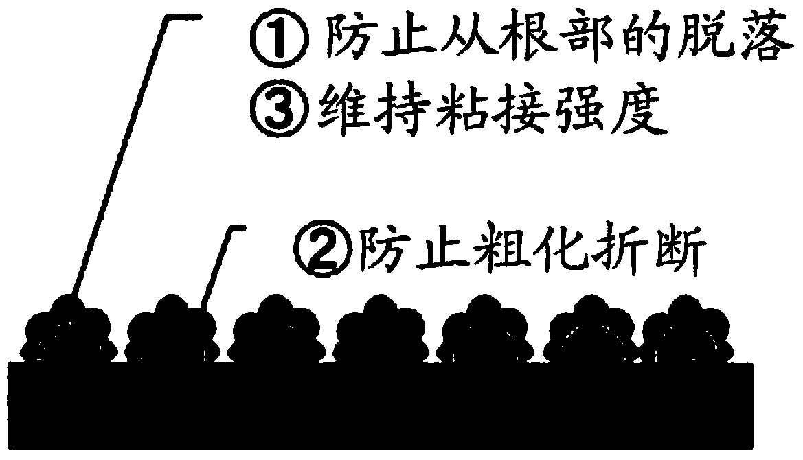
A technology of printed circuit and copper foil, applied in the direction of printed circuit, printed circuit, printed circuit manufacturing, etc., can solve the problems of etching residue, roller pollution, particle shedding, etc., and achieve the effect of good etching.

Active Publication Date: 2014-07-30
JX NIPPON MINING & METALS CO LTD
View PDF14 Cites 3 Cited by
  • Summary
  • Abstract
  • Description
  • Claims
  • Application Information

AI Technical Summary

Problems solved by technology

[0019] However, since the shape of the most basic roughened particles made of copper-cobalt-nickel alloy formed on the surface of the copper foil is dendritic, it peels off from the top or root of the branch, resulting in what is generally called powder drop problem
[0020] This powder falling phenomenon is a troublesome problem. Although the copper-cobalt-nickel alloy-pl

Method used


Image

  • Copper foil for printed circuit
  • Copper foil for printed circuit
  • Copper foil for printed circuit

Examples


Embodiment 1- Embodiment 6

[0132] On the rolled copper foil, a primary particle layer (Cu) and a secondary particle layer (copper-cobalt-nickel alloy plating) were formed in the condition range shown below.

[0133] The plating solution composition and plating conditions used are shown below.

[0134] [Bath composition and plating conditions]

[0135] (A) Formation of primary particle layer (Cu plating)

[0136]

[0137] (B) Formation of secondary particle layer (Cu-Co-Ni alloy plating)

[0138]

[0139] The above-mentioned conditions for the formation of the primary particle layer (Cu plating) and the formation of the secondary particle layer (Cu-Co-Ni alloy plating) were adjusted so that the average height of the unevenness of the roughened surface observed with a laser microscope was 1500 or more. For the measurement of the surface area, the measurement method using the above-mentioned laser microscope was used.

Embodiment 1

[0154] Embodiment 1 is to form the current density of the primary particle as 65A / dm 2 and 20A / dm 2 , Set the Coulomb amount to 80As / dm 2 and 30As / dm 2 In the case of , the current density for forming secondary particles is set to 28A / dm 2 , set the Coulomb amount to 20As / dm 2 Case.

[0155] Furthermore, the current density and the coulomb quantity for forming primary particles are two stages, and in the case of forming primary particles, two stages of electroplating are generally required. That is, the plating conditions for the formation of nuclei particles in the first stage and the electroplating for the growth of nuclei particles in the second stage.

[0156] The initial plating conditions are plating conditions for the formation of nucleation particles in the first stage, and the subsequent plating conditions are plating conditions for the growth of nuclei particles in the second stage. The same applies to the following examples and comparative examples, and thus d...

Embodiment 2

[0159] Embodiment 2 is to form the current density of the primary particle as 65A / dm 2 and 2A / dm 2 , Set the Coulomb amount to 80As / dm 2 and 4As / dm 2 In the case of , the current density for forming secondary particles is set to 25A / dm 2 , set the Coulomb amount to 15As / dm 2 Case.

[0160] As a result, the average particle diameter of the primary particles was 0.40 μm, the average particle diameter of the secondary particles was 0.15 μm, and the average height of the irregularities on the roughened surface observed with a laser microscope was 1556, which satisfied the conditions of the present invention. .

[0161] As a result, it has the following characteristics, that is, less powder shedding, high normal peel strength of 0.89kg / cm, heat resistance deterioration rate (measure the peel strength after heating at 180°C for 48 hours after the normal peel measurement, and set the difference as is the degradation rate) as small as 30% or less.


PUM

PropertyMeasurementUnit
The average particle sizeaaaaaaaaaa
Normal peel strengthaaaaaaaaaa

Abstract

The invention relates to a copper foil for the printed circuit, which forms a ternary alloy particle layer consisting of copper, cobalt and nickel on the first particle layer after the first particle layer is formed on the surface of the copper foil. The invention is characterized by coursing a certain area of the processing area until the average value of the height column diagram which can be detected by a laser microscope is aboeve 1500. The invention also provides the copper foil for the printing circuit. The average particle radius of the first particle is 0.25-0.45mum, and average particle radius of the secondary particle layer consisting of the copper, the cobalt and the nickel is smaller than the 0.35mum. The invention forms a secondary particle layer consisting of the cooper, the cobalt and the nickel after the first particle is formed, the average value of the height column diagram which can be detected by the laser microscope after coursing processing is set to be over 1500 so as to reduce the generation of the coming-off powder from the copper foul, enhance the stripping intensity and improve the high temperature resistance.

Description

technical field [0001] The present invention relates to a copper foil for a printed circuit, in particular to a copper foil for a printed circuit in which a primary particle layer of copper is formed on the surface of the copper foil, and then formed thereon by copper-cobalt-nickel alloy plating. The secondary particle layer can reduce the generation of powder falling from the copper foil, improve the peel strength, and improve the heat resistance. [0002] The copper foil for printed circuits of the present invention is particularly suitable for, for example, fine pattern printed circuits and flexible printed wiring boards (Flexible Printed Circuit). Background technique [0003] Copper and copper alloy foil (hereinafter referred to as copper foil) contribute greatly to the development of electrical / electronic related industries, and are indispensable as printed circuit materials in particular. Copper foil for printed circuits is generally produced by laminating and bondin...

Claims


Application Information

Patent Timeline
IPC IPC(8): C25D7/06H05K1/09
CPCC25D3/38C25D3/58C25D5/12C25D7/0614C25D5/605C25D5/617H05K1/09H05K3/384H05K2201/0355
Inventor 新井英太三木敦史
Owner JX NIPPON MINING & METALS CO LTD
Why Eureka
Try Eureka