
Method and device for realizing combustible gas multi-point laser plasma ignition based on microlens array

A micro-lens array and plasma technology, which is applied to gas turbine devices, jet propulsion devices, rocket engine devices, etc., can solve problems such as combustion chamber explosion and impact on aircraft safety.

Inactive Publication Date: 2014-08-13
HARBIN INST OF TECH
View PDF7 Cites 5 Cited by
  • Summary
  • Abstract
  • Description
  • Claims
  • Application Information

AI Technical Summary

Problems solved by technology

In the field of aerospace, there are high requirements for the ignition reliability of the engine. Ignition failure can easily generate a destructive pressure peak in the combustion chamber, and even cause the combustion chamber to explode, affecting the safety of the aircraft.

Method used


Image

  • Method and device for realizing combustible gas multi-point laser plasma ignition based on microlens array

Examples


specific Embodiment approach 1

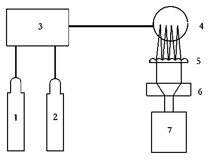
[0016] Specific implementation mode one: as figure 1 As shown, the device for multi-point laser plasma ignition of combustible gas based on the microlens array provided by this embodiment includes a fuel gas source 2, an oxidant gas source 1, a gas distribution system 3, a nozzle 4, and sequentially arranged along the direction of the optical axis. Laser 7, beam expander collimation system 6 and microlens array 5; the gas outlets of fuel gas source 2 and oxidant gas source 1 are connected with the air inlet of gas distribution system 3, and the gas outlet of gas distribution system 3 is connected with the nozzle 4 The air inlets are connected, and the nozzle 4 is located at the focal length of the microlens array 5 . When in use, the combustible gas is passed into the nozzle; the laser emits laser light, which is incident on the microlens array after beam expansion and collimation, and induces multiple plasmas in the mixed gas above the nozzle axis, and ignites the combustible...

specific Embodiment approach 2

[0017] Specific embodiment two: the difference between this embodiment and specific embodiment one is that the fuel is one of methane, propane, hydrogen, and natural gas; the oxidant is a nitrogen / oxygen mixture, and the volume fraction of oxygen is 5-100 %.

specific Embodiment approach 3

[0018] Specific embodiment three: the difference between this embodiment and specific embodiments one and two is that the laser is a kind of pulsed solid-state laser and pulsed excimer laser, and the laser wavelength is 1064 nm and its high-order frequency multiplication, 694.3 nm and Its high-order frequency doubling, one of 308 nm and 248 nm, the laser repetition frequency is 10-1000 Hz, and the laser pulse energy is 5-2000 mJ.


PUM

PropertyMeasurementUnit
Focal lengthaaaaaaaaaa
Diameteraaaaaaaaaa

Abstract

The invention discloses a method and a device for realizing combustible gas multi-point laser plasma ignition based on a microlens array. The method comprises the steps of 1, feeding combustible gas into a nozzle; 2, enabling a laser device to emit laser which is incident to the microlens array after being expanded and collimated, inducing to generate a plurality of plasmas in mixed fuel gas above the axial line of the nozzle, and igniting the combustible gas. The device comprises a fuel gas source, an oxidizing agent gas source, a gas distribution system, the nozzle, and the laser device, a beam expansion and collimation system and the microlens array which are arranged in sequence along the optical axis direction, wherein gas outlets of the fuel gas source and the oxidizing agent gas source are connected with the gas inlet of the gas distribution system; the gas outlet of the gas distribution system is connected with the gas inlet of the nozzle; the nozzle is positioned at a focal length of the microlens array. By adopting the method and the device, the reliability of laser plasma ignition can be greatly improved.

Description

technical field [0001] The invention relates to a method for realizing combustible gas multi-point laser plasma ignition and a device for realizing the method. Background technique [0002] In order to improve the ignition reliability of the lean-burn combustion system, the traditional electric spark plug ignition system needs to work at a voltage of up to tens of kV, which easily causes electrode corrosion and shortens the life of the spark plug. Laser plasma ignition has the advantages of convenient and controllable ignition position and ignition time, wide application range of equivalence ratio, and good electromagnetic compatibility. In the field of aerospace, there are high requirements for the ignition reliability of the engine. Ignition failure can easily generate a destructive pressure peak in the combustion chamber, and even cause the combustion chamber to explode, affecting the safety of the aircraft. Therefore, how to improve the ignition reliability of combustib...

Claims


Application Information

Patent Timeline
IPC IPC(8): F02C7/264F02K9/95
Inventor 李晓晖于欣彭江波于杨樊荣伟陈德应
Owner HARBIN INST OF TECH
Learn More