Sensitivity enhancement demodulation method and device of fiber optical Bragg grating strain sensor

A Bragg fiber and grating strain technology, applied in the direction of using optical devices, using optical devices to transmit sensing components, measuring devices, etc., can solve problems such as low precision, and achieve enhanced strain sensitivity, improved strain sensing sensitivity, and effective strain sensitivity. Enhanced effect

Inactive Publication Date: 2014-09-03
SHANGHAI JIAO TONG UNIV
View PDF6 Cites 7 Cited by
  • Summary
  • Abstract
  • Description
  • Claims
  • Application Information

AI Technical Summary

Problems solved by technology

However, this technology has low precision due to its intrinsically limited temperature sensitivity sensing characteristics and the wide spectrum of its traditional demodulation structure.

Method used


Image

  • Sensitivity enhancement demodulation method and device of fiber optical Bragg grating strain sensor
  • Sensitivity enhancement demodulation method and device of fiber optical Bragg grating strain sensor
  • Sensitivity enhancement demodulation method and device of fiber optical Bragg grating strain sensor

Examples


Embodiment 1

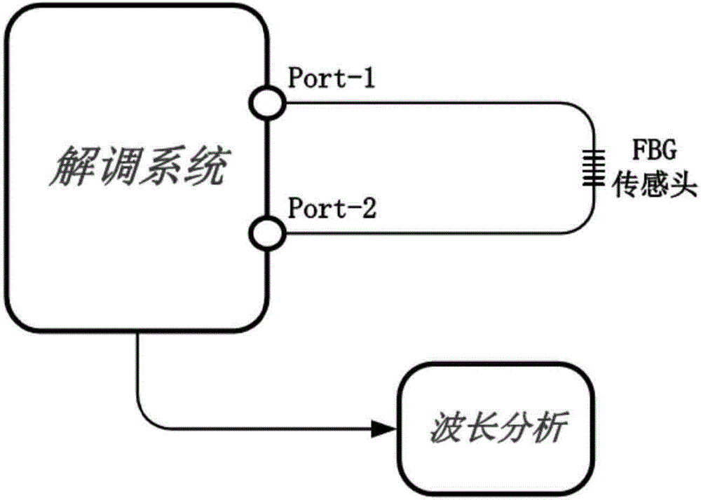
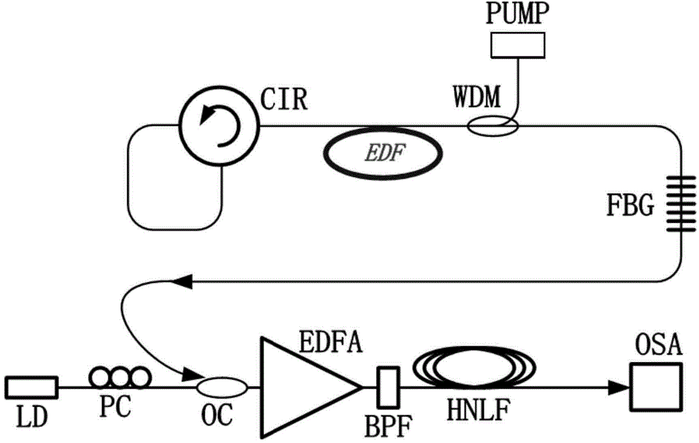
[0034] Such as figure 1 and 2As shown, the optical fiber sensing demodulation system described in this embodiment includes: a circulator CIR connected in series, an erbium-doped fiber EDF, a wavelength division multiplexer WDM, a single-frequency laser LD and a polarization controller connected in series in sequence PC, coupler OC and at least one stage of erbium-doped fiber amplifier EDFA and its nonlinear optical fiber HNLF, wherein: the output end of the wavelength division multiplexer WDM and the input end of the coupler OC are respectively used as the first port and the second port of the device The two ports are connected to both ends of the fiber Bragg grating FBG, the input end of the wavelength division multiplexer WDM is equipped with a 980nm pump laser PUMP, and the output end of the nonlinear fiber HNLF is equipped with an optical spectrum analyzer OSA

[0035] An optical filter BPF is arranged between the erbium-doped fiber amplifier EDFA and the nonlinear fiber ...

Embodiment 2

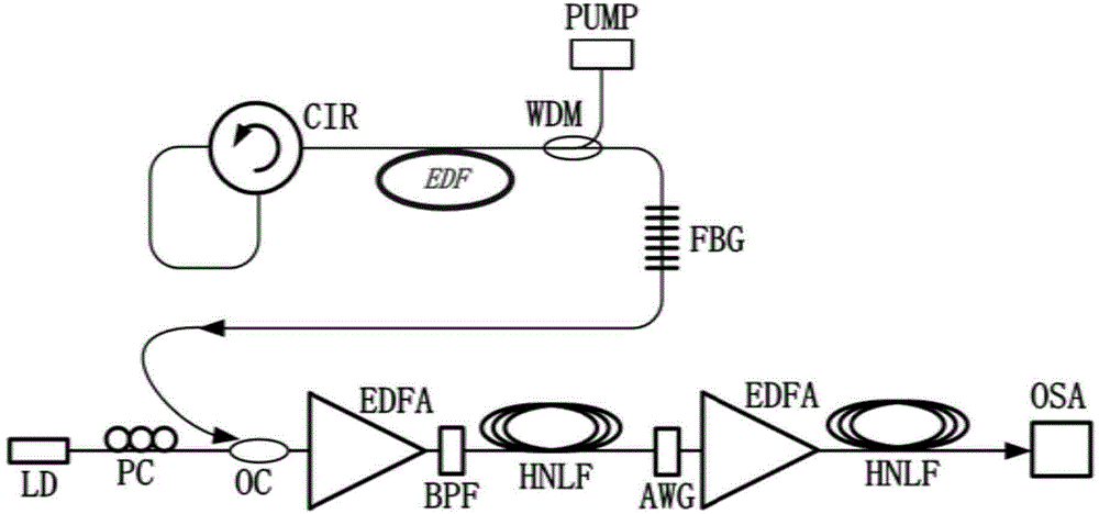
[0039] Such as image 3 As shown, it is the structural diagram of the optical fiber sensing demodulation system described in the present embodiment, when adopting multi-stage at least one-stage erbium-doped fiber amplifier EDFA and its nonlinear optical fiber HNLF, then in the rear stage erbium-doped fiber amplifier EDFA The input end is equipped with an arrayed waveguide grating AWG.

[0040] According to this embodiment: the erbium-doped fiber is pumped by a 980nm laser, and one end of the radiated spontaneous radiation is reflected back by the reflective ring mirror of the circulator structure, and the other end is connected to the FBG. The FBG has a reflectivity of 50%, so that at the FBG resonance wavelength A part of the position is reflected and a part is transmitted, and the transmission end of the FBG outputs laser light. The output laser wavelength is completely consistent with the resonance wavelength of the FBG.

[0041] The output laser is combined with the outp...


PUM

PropertyMeasurementUnit
Lengthaaaaaaaaaa
Lengthaaaaaaaaaa
Nonlinear coefficientaaaaaaaaaa

Abstract

The invention relates to a sensitivity enhancement demodulation method and device of a fiber optical Bragg grating strain sensor and belongs to the technical field of optical detection devices. The method comprises the following steps: outputting original laser which is as the same as resonant wavelength of FBG (Fiber Bragg Grating) and changes synchronously in real time by an optical fiber laser as pump light; after combining the pump light and signal laser at another wavelength, carrying out chirped amplification of frequency in a non-linear system to realize high order four-wave mixing; and finally, realizing high sensitivity detection of wavelength drift and corresponding strain of the original laser through wavelength analysis of idle light. According to the invention, sensor demodulation with high strain sensitivity can be obtained at wavelength near 1550nm, and high strain sensitivity which is higher than intrinsic sensitivity of FBG can be obtained in the demodulating process based on common FBG, so that the method and device provided by the invention are suitable for sense application of high strain sensitivity.

Description

technical field [0001] The present invention relates to a device and method in the technical field of optical detection devices, in particular to a sensitivity enhancement demodulation method and device for a Fiber Bragg Grating (FBG) strain sensor. Background technique [0002] In recent years, fiber optic sensing has been applied in a wide range of fields due to its advantages of anti-radiation, anti-interference, anti-corrosion, low cost, ultra-small, pollution-free, safe and reliable. In particular, fiber optic sensors using FBG can achieve high-sensitivity temperature and strain measurements, which can be used for high temperature monitoring, building health monitoring, fire safety monitoring, deformation detection of dams and bridges, etc. [0003] Generally speaking, the strain sensitivity of 1pm / με can be obtained by using the fiber Bragg grating of traditional single-mode fiber [B.Lee, "Review of the present status of optical fiber sensors," Opt.Fiber Technol.9,57-7...

Claims


Application Information

Patent Timeline
IPC IPC(8): G01B11/16G01D5/353
Inventor 何祖源杜江兵樊昕昱刘庆文
Owner SHANGHAI JIAO TONG UNIV
Why Eureka
Try Eureka