Oxygen-enriched combustion pulverized coal boiler integrating chemical-looping high-temperature air separation oxygen production and CO2 gathering method

An integrated chemical and oxygen-enriched combustion technology, applied in the energy field, can solve the problems of large investment, low economic and energy utilization efficiency, and high energy consumption, and achieve the goals of improving heat utilization, reducing oxygen power consumption, and improving power generation efficiency Effect

Inactive Publication Date: 2014-09-10
SOUTHEAST UNIV
View PDF8 Cites 24 Cited by
  • Summary
  • Abstract
  • Description
  • Claims
  • Application Information

AI Technical Summary

Problems solved by technology

Traditional oxygen-enriched combustion requires large-scale air separation to produce oxygen, which requires large investment and high energy consumption, which reduces the economy and energy utilization efficien...

Method used


Image

  • Oxygen-enriched combustion pulverized coal boiler integrating chemical-looping high-temperature air separation oxygen production and CO2 gathering method

Examples


Embodiment 1

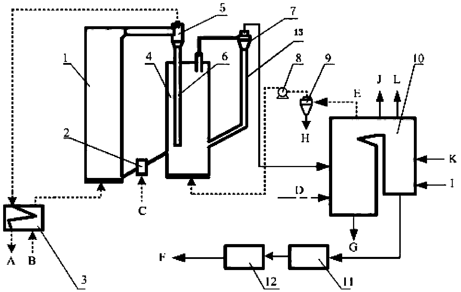
[0026] An oxygen-enriched pulverized coal boiler with integrated chemical chain high-temperature air separation for oxygen production, such as figure 1As shown, it includes an air preheater 3, an oxidation reactor 1, a first cyclone separator 5, an overflow tank 2 with a loose tuyere, a reduction reactor 4, a second cyclone separator 7, and a high-temperature flue gas induced draft fan 8 , high-temperature dust collector 9, coal-fired boiler 10, low-temperature dust collector 11, flue gas cooling compression purification device 12. The air preheater 3 is connected to the inlet of the lower end of the oxidation reactor 1, the lower end of the oxidation reactor 1 is connected to the reduction reactor 4 through the overflow tank 2 provided with a loose tuyere, and the outlet of the upper end of the oxidation reactor 1 is connected to the first cyclone separator 5 connected, the upper end outlet of the first cyclone separator 5 is connected with the air preheater 3, the feeding pi...

Embodiment 2

[0031] CO 2 A capture method comprising the steps of:

[0032] Step 1. The air B is heated by the air preheater 3 and then passed into the oxidation reactor 1, where it reacts with the low-valence oxygen carrier at 600-1300°C, and the low-valence oxygen carrier is oxidized into a corresponding high-valence state The air B becomes the high-temperature oxygen-poor air A, and the reaction product is separated by the first cyclone separator 5. The high-temperature oxygen-deficient air A enters the air preheater 3 to heat the air B, and discharges it into the atmosphere after cooling down. Oxygen enters the reduction reactor 4 from the feed pipe 6 of the first cyclone separator 5 . Oxygen carriers include manganese-based oxygen carriers, cobalt-based oxygen carriers, copper-based oxygen carriers or perovskite oxides. Manganese-based oxygen carrier is Mn 2 o 3 \Mn 3 o 4 , the cobalt-based oxygen carrier is Co 3 o 4 \CoO, the copper-based oxygen carrier is CuO\Cu 2 O, perovs...


PUM


Abstract

The invention discloses an oxygen-enriched combustion pulverized coal boiler integrating chemical-looping high-temperature air separation oxygen production. The pulverized coal boiler comprises an air preheater, an oxidation reactor, a first cyclone separator, an overflow box with a loose tuyere, a reduction reactor, a second cyclone separator, a high-temperature flue gas draft fan, a high-temperature dust catcher, a coal-fired boiler, a low-temperature dust catcher and a flue gas cooling compression and purification device. The invention also provides a CO2 gathering method using the boiler. According to the invention, the oxygen-enriched combustion pulverized coal boiler is integrated with chemical-looping high-temperature air separation oxygen production, and can effectively reduce the oxygen production power consumption of oxygen-enriched combustion, improve the power generation efficiency of an oxygen-enriched combustion set and realizes gathering of CO2 as compared with an existing boiler.

Description

technical field [0001] The invention relates to the field of energy technology, in particular to an oxygen-enriched combustion pulverized coal boiler and a CO 2 capture method. Background technique [0002] CO in Earth's atmosphere since industrial civilization 2 The concentration has risen sharply due to human production activities. CO 2 As a typical greenhouse gas, it directly leads to the greenhouse effect. With the increasing global climate change in recent years, CO 2 Capture and storage (CCS) technology has become a hot issue in the field of energy and environmental science. Chemical looping combustion is a CO2 developed in the 1980s 2 Separation and capture technology. Coal-fired power plant CO 2 The emission has the characteristics of low partial pressure, large flow and high temperature, and is a large-scale CO emission reduction 2 the most important areas. Under the conventional air combustion method, most of the flue gas components are nitrogen, and the ...

Claims


Application Information

Patent Timeline
IPC IPC(8): F23C7/00F23L7/00C01B31/20C01B32/50
CPCY02E20/34Y02P20/129
Inventor 向文国顾鹏飞
Owner SOUTHEAST UNIV
Why Eureka
Try Eureka