Organic light emission diode and preparation method thereof
An electroluminescent device and luminescent technology, applied in the field of electric light sources, can solve problems such as short service life, poor OLED stability, and increased bandgap width, and achieve the effects of reducing production costs, high qualified rate of finished products, and improving production efficiency
- Summary
- Abstract
- Description
- Claims
- Application Information
AI Technical Summary
Problems solved by technology
Method used
Image

Examples
preparation example Construction
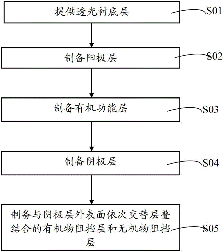
[0050] Correspondingly, the embodiment of the present invention also provides a preparation method of the above-mentioned organic electroluminescence device. The process flow chart of the method is as image 3 Therefore, see also Figure 1~2 , the method includes the following steps:
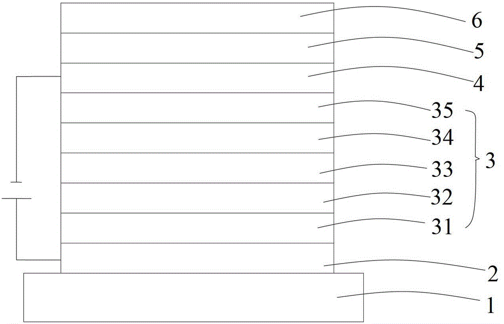
[0051] S01. Provide a light-transmitting substrate layer 1;
[0052] S02. Prepare the anode layer 2: plate the anode layer 2 on the surface of the transparent substrate layer 1 in step S01;
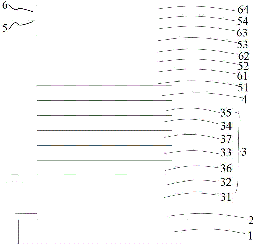
[0053] S03. Preparation of organic functional layer 3: In step S02, the surface opposite to the surface of the anode layer 2 prepared with the light-transmitting substrate layer 1 is sequentially plated with a hole injection layer 31, a hole transport layer 32, a light-emitting layer 33, and an electron transport layer 34. , the electron injection layer 35, forming the organic functional layer 3;
[0054] S04. Prepare the cathode layer 4: plate the cathode layer 4 on the outer surface of the organic fun...
Embodiment 1
[0077] An organic electroluminescence device, its structure is: glass substrate / ITO / MoO 3 :NPB / TCTA / TPBI:Ir(ppy) 3 / Bphen / CsN 3 :Bphen / Al / (TPD:Bphen / Sb 2 Se 3 :MgO:Sb 2 Te 3 ) 6 .
[0078] The preparation method of the organic electroluminescence device comprises the following steps:
[0079] a) Pre-treatment of ITO glass substrate: cleaning with acetone→cleaning with ethanol→cleaning with deionized water→cleaning with ethanol, all of them are cleaned with an ultrasonic cleaner, and the single washing is cleaned for 5 minutes, then blown dry with nitrogen, and dried in an oven for later use; The cleaned ITO glass also needs surface activation treatment to increase the oxygen content of the conductive surface layer and improve the work function of the conductive layer surface; the thickness of ITO is 100nm;
[0080]b) Preparation of the organic functional layer: sequentially coat the outer surface of the ITO layer in step a) with a hole injection layer, a hole transport...
Embodiment 2
[0091] An organic electroluminescence device, its structure is: glass substrate / ITO / MoO 3 :NPB / TCTA / TPBI:Ir(ppy) 3 / Bphen / CsN 3 :Bphen / Al / (BCP:NPB / MoSe 2 : Bi 2 Te:Al 2 o 3 ) 6 .
[0092] The preparation method of the organic electroluminescence device comprises the following steps:
[0093] a), b), c) are the same as in Example 1;
[0094] d) Fabrication of the organic barrier layer: the organic barrier layer is made of NPB as the hole transport material and BCP doped co-evaporation as the electron transport material, wherein the hole transport material accounts for 50% of the total molar percentage of the organic barrier layer material, and vacuum Prepared by evaporation, vacuum degree 5×10 -5 Pa, evaporation rate Thickness 250nm;
[0095] e) Preparation of inorganic barrier layer: the inorganic barrier layer is made of telluride, selenide and oxide doped magnetron sputtering, and the selenide is MoSe 2 , the telluride is Bi 2 Te, the oxide is Al 2 o 3 , wher...
PUM
| Property | Measurement | Unit |
|---|---|---|
| Thickness | aaaaa | aaaaa |
| Thickness | aaaaa | aaaaa |
| Thickness | aaaaa | aaaaa |
Abstract
Description
Claims
Application Information