Step-by-step waste heat recovery system and method for electric furnace flue gas on whole temperature section

A recovery system and flue gas technology, applied in the field of step-by-step waste heat recovery system in the full temperature section of electric furnace flue gas, can solve the problems of no recovery, low efficiency of waste heat recovery, no heat recovery, etc., to improve utilization efficiency and discharge flue gas volume Large, high temperature effects

Active Publication Date: 2014-09-24
SHANGHAI BAOSTEEL ENERGY TECH
View PDF6 Cites 10 Cited by
  • Summary
  • Abstract
  • Description
  • Claims
  • Application Information

AI Technical Summary

Problems solved by technology

[0005] The purpose of the present invention is to provide a step-by-step waste heat recovery system in the full temperature section of electric furnace flue gas to solve the problem that the existing electric furnace waste heat recovery system does not recover the heat of high-temperature flue gas between the electric furnace and the combustion settling chamber, which leads to waste heat recovery low efficiency technical problems
[0006] Another object of the present invention is to provide the above-mentioned method for recovering waste heat by the waste heat recovery system in the full-temperature section of the electric furnace flue gas, so as to solve the problem that the existing electric furnace waste heat recovery system does not control the heat of the high-temperature flue gas between the electric furnace and the combustion settling chamber recovery, which leads to the technical problem of low efficiency of waste heat recovery

Method used


Image

  • Step-by-step waste heat recovery system and method for electric furnace flue gas on whole temperature section

Examples


Embodiment 1

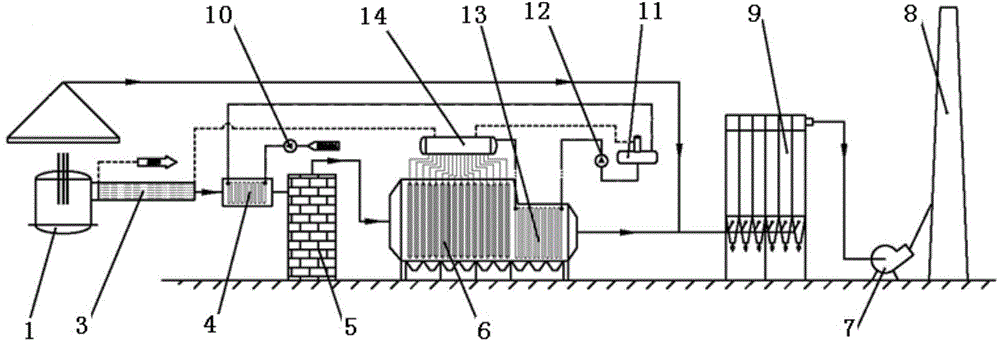
[0035] see figure 1, the waste heat recovery system of the electric furnace flue gas full temperature section step by step of the present invention includes a flue gas subsystem and a soda water subsystem. Settling chamber 5 with heat storage device, evaporator 6, economizer 13, low-temperature economizer (not shown), dust collector 9, fan 7 and chimney 8; the steam-water subsystem includes water pump 10, deaerator 11, Boiler feed water pump 12 and steam drum 14, water pump 10 is connected with low pressure feed water heat exchanger 4, low pressure feed water heat exchanger 4 is connected with deaerator 11, deaerator 11, boiler feed water pump 12, low temperature economizer, coal economizer The device 13 is sequentially connected with the steam drum 14, and the steam drum 14 is respectively connected with the evaporator 6 and the vaporization flue 3. During operation, the high-temperature flue gas produced by the electric furnace 1 passes through the vaporization flue 3, the ...

Embodiment 2

[0041] The waste heat recovery system of the electric furnace flue gas full temperature section step by step of the present invention includes a flue gas subsystem and a soda water subsystem. device and smoke exhaust device; the steam water subsystem includes water pump, deaerator, boiler feed water pump and steam drum, the water pump is connected with the deaerator, the deaerator, boiler feed water pump, economizer are connected with the steam drum in turn, and the steam drum is respectively Connect with evaporator and vaporization flue. When working, the high-temperature flue gas generated by the electric furnace passes through the flue gas circulation channel formed by the vaporization flue, settling chamber, evaporator, economizer, dust removal device and smoke exhaust device, and then becomes low-temperature flue gas to be discharged, so as to achieve the purpose of recovering waste heat . At the same time, the pure water pumped by the water pump is turned into steam for...

Embodiment 3

[0047] The method for recovering waste heat by the step-by-step waste heat recovery system of the electric furnace flue gas full temperature section of the present invention comprises the following steps:

[0048] a. The high-temperature flue gas produced by the electric furnace enters the low-pressure feed water heat exchanger for heat exchange and cooling after passing through the vaporization flue, and then enters the settling chamber. The CO combustible gas contained in the flue gas is burned in the settling chamber equipped with a heat storage device, generating high At the same time, the heat storage device stores the heat generated by combustion; the flue gas passes through the evaporator and economizer for heat exchange and cooling, then enters the low-temperature economizer for heat exchange and cooling again, and then enters the dust collector. chimney emissions;

[0049] b. The water pumped by the water pump is heated by the low-pressure feed water heat exchanger an...


PUM


Abstract

The invention provides a step-by-step waste heat recovery system and method for electric furnace flue gas on the whole temperature section. The step-by-step waste heat recovery system provided by the invention comprises a flue gas subsystem and a steam-water subsystem, wherein the flue gas subsystem comprises an electric furnace, a vaporization flue duct, a low-pressure water supply heat exchanger, a settling chamber with a heat accumulation device, an evaporator, a coal economizer, a low-temperature coal economizer, a dust removal device and a flue gas extractor; the steam-water subsystem comprises a water pump, a deaerator, a boiler feed pump device a steam pocket; the water pump is connected with the low-pressure water supply heat exchanger; the low-pressure water supply heat exchanger is connected with the deaerator; the deaerator, the boiler feed pump, the low-temperature coal economizer, the coal economizer and the steam pocket are connected in sequence; the steam pocket is connected with the evaporator and the vaporization flue duct respectively. Compared with the prior art, owing to the arrangement of the vaporization flue duct between the electric furnace and the combustion settling chamber, the step-by-step waste heat recovery system effectively recovers part of heat of high-temperature flue gas between the electric furnace and the combustion settling chamber, and improves the waste heat recovery efficiency and the utilization efficiency of energy sources.

Description

technical field [0001] The invention relates to the technical field of recovery and utilization of industrial waste heat, in particular to a system and method for stepwise recovery of waste heat in the full temperature section of electric furnace flue gas. Background technique [0002] At present, in order to further reduce the cost of electric furnace steelmaking in electric furnaces and converters in domestic iron and steel enterprises, the molten iron mixed with scrap steel smelting mode generally appears in the electric furnace process, and the ratio of molten iron can be as high as 70-90%, showing the trend of "converterization" of electric furnace equipment. With the increase of the proportion of molten iron in the electric furnace and the reduction of the amount of scrap steel, the concentration of CO in the flue gas and flue gas of the electric furnace will increase and the temperature of the flue gas will increase. Therefore, it is reasonable to effectively control t...

Claims


Application Information

Patent Timeline
Patent Type & Authority Applications(China)
IPC IPC(8): F27D17/00F22B1/18F22G1/00
CPCY02P10/25
Inventor 曹先常陈志良杨文滨孔令斌
Owner SHANGHAI BAOSTEEL ENERGY TECH
Why Eureka
Try Eureka