A Dielectric-Piezoelectric Composite Film Phase Shifter

A piezoelectric composite, dielectric film technology, applied in circuits, electrical components, waveguide-type devices, etc., can solve the problems of large microwave loss, high power consumption, and high working field strength, and achieve low driving voltage, stable performance, and low power consumption. The effect of loss

Active Publication Date: 2017-01-04
深圳威科射频技术有限公司
View PDF3 Cites 0 Cited by
  • Summary
  • Abstract
  • Description
  • Claims
  • Application Information

AI Technical Summary

Problems solved by technology

The PIN diode phase shifter realizes phase shift by turning on or off a section of transmission line through two different switch states in forward bias and reverse bias. It is easy to use digital signal control and works fast, but it consumes a lot of power, especially The power capacity in the microwave frequency band is relatively small; the ferrite phase shifter mainly changes the magnetic permeability of the ferrite in the waveguide by applying an external magnetic field, thereby changing the phase velocity of the electromagnetic wave to obtain different phase shifts, and has a large power capacity. The insertion loss is relatively small, and the degree of phase shift can also be large, but because the excitation coil is required to provide the driving current, the volume is very large and the response speed is relatively slow; the ferroelectric phase shifter changes the dielectric constant of the ferroelectric material, In order to achieve the purpose of shifting, it has the advantages of fast scanning speed, small size and light weight, but the ferroelectric material has a limited dielectric tuning range and high microwave loss. When the ferroelectric thin film is applied to a dielectric resonator, the loss should be lower than 1dB, that is to say, the dielectric loss of the ferroelectric film should be lower than 0.005 at 10 GHz. Obviously, the existing ferroelectric film cannot meet this requirement; the working field is high and cannot meet the material requirements of the development of communication technology

Method used


Image

  • A Dielectric-Piezoelectric Composite Film Phase Shifter
  • A Dielectric-Piezoelectric Composite Film Phase Shifter
  • A Dielectric-Piezoelectric Composite Film Phase Shifter

Examples


Embodiment Construction

[0031] The present invention will be described in detail below in conjunction with the accompanying drawings.

[0032] The function of the phase shifter is to shift the phase of the signal by an angle. Its working principle is different according to different components. Such as a transistor circuit, a control signal can be added to the input to control the phase shift; in some circuits, the delay of the resistance-capacitance circuit is used to achieve phase shift; in the single-chip control system, the internal timer can also be used to achieve the purpose of phase shift.

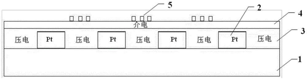
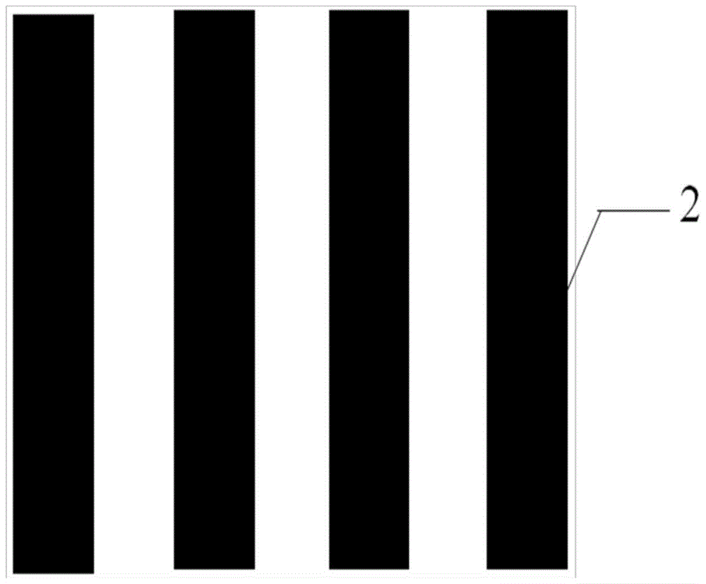
[0033] Refer to attached figure 1 , the dielectric-piezoelectric composite thin-film phase shifter of the present invention, which includes a dielectric substrate 1, a strip-shaped drive electrode 2, a piezoelectric film 3, a dielectric film 4 and an interdigitated coplanar waveguide transmission line 5, and a strip-shaped drive electrode 2 is set on the dielectric substrate 1, the piezoelectric film 3 ...


PUM


Abstract

The invention belongs to the technical field of microwave engineering and particularly relates to a dielectric-piezoelectric composite film phase shifter. The dielectric-piezoelectric composite film phase shifter comprises a dielectric substrate, a strip-shaped driving electrode, a piezoelectric film, a dielectric film and an interdigital coplanar waveguide transmission line. The strip-shaped driving electrode is arranged on the dielectric substrate, the dielectric substrate is deposited on the strip-shaped driving electrode, the dielectric film is deposited on the piezoelectric film, and the interdigital coplanar waveguide transmission line is deposited on the dielectric film. According to the phase shifter, the size of the dielectric film is controlled through the inverse piezoelectric effect of the piezoelectric film, and thus the phase shifting purpose is achieved. Through composition of the dielectric film and the piezoelectric film, loss of the phase shifter in the microwave section can be reduced, and the dielectric-piezoelectric composite film phase shifter has the advantages of being simple in technology, small in size and loss, low in driving voltage, stable in performance and the like.

Description

technical field [0001] The invention belongs to the technical field of microwave engineering, and in particular relates to a dielectric-piezoelectric composite film phase shifter. Background technique [0002] With the development of wireless communication technology, the resources of available frequency bands are getting tighter and tighter, and the frequency bands that can be used by various wireless communication systems are getting narrower and narrower, which puts forward higher requirements for wireless communication technology, so high Phased array radar with measurement accuracy, high resolution capability and high observation capability has become a research hotspot. The phase shifter is an important basis for the development of phased array radar. The phase shifter in the microwave band can meet these requirements. The physical advantages of millimeter wave are shorter wavelength, wide operating frequency band, and high resolution for target tracking and identifica...

Claims


Application Information

Patent Timeline
Patent Type & Authority Patents(China)
IPC IPC(8): H01P1/18
Inventor 周静吴智陈文沈杰胡麟吕纯
Owner 深圳威科射频技术有限公司
Why Eureka
Try Eureka