
Reduction ironmaking process of bottom heating type fixed furnace hearth

A hearth and process technology, which is applied in the field of bottom heating fixed hearth reduction ironmaking process, can solve the problems of electrode consumption, difficult direct reduction of iron, sponge iron gangue and high sulfur content, so as to prevent secondary oxidation and reduce production costs low effect

Inactive Publication Date: 2014-10-15
WISDRI ENG & RES INC LTD
View PDF3 Cites 0 Cited by
  • Summary
  • Abstract
  • Description
  • Claims
  • Application Information

AI Technical Summary

Problems solved by technology

Due to the strict requirements on raw materials and fuels, the high investment and operating costs per unit capacity, the difficulty in stable operation, and the small production scale (maximum 150,000 t / year), it is difficult to become the main process for the development of direct reduced iron in my country
[0006] Rotary hearth furnaces have achieved industrial production in the treatment of dust containing Fe, Zn, Cr, and Ni in iron and steel plants. The disadvantages are that the sponge iron (DRI) gangue and sulfur content are high, which leads to an increase in the amount of steelmaking slag in the electric furnace and electrode consumption. Difficult to be directly used in the production of direct reduced iron for steelmaking
Secondly, the rotary hearth furnace adopts the open flame heating method to heat the charge. Since the fuel combustion is an oxidizing atmosphere, and the reduction of iron oxides requires a reducing atmosphere, the open flame heating method usually has the difficulty of controlling the furnace atmosphere, and the reduced products are easy to be secondary. The problem of oxidation affects the final quality of sponge iron

Method used


Image

  • Reduction ironmaking process of bottom heating type fixed furnace hearth

Examples


Embodiment 1

[0033] Raw material preparation: Mix the fine iron powder and make pellets on the pelletizer, the diameter of the pellets is 20mm. The lump coal is crushed into small pieces of coal about 24mm in diameter.

[0034] Cloth: Use a trolley or a cloth belt table to cloth, firstly distribute the lump coal evenly on the hearth, and then distribute the balls on the lump coal;

[0035] Reduction area setting: hearth setting is 6m×6m. The number of hearths can be set according to the annual production requirements;

[0036] Combustion area setting: coal is used as fuel, the fuel is put into the furnace through the furnace door, ignited and burned, and a grate is provided at the lower part of the furnace to facilitate ash discharge;

[0037] Raw material reduction: In the later stage of furnace charge reduction, the furnace temperature is controlled at 1100-1300°C, and the optimal temperature is 1200°C;

[0038] Discharge: use scraper discharge. The metallization rate of the discharg...


PUM


Abstract

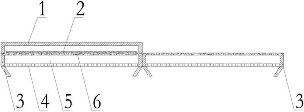
The invention discloses a reduction ironmaking process of a bottom heating type fixed furnace hearth. A furnace is arranged below the furnace hearth; a furnace cover for sealing a material layer is arranged above the furnace hearth; heat is generated in the furnace through the fuel combustion, and is transferred and diffused to the material layer of the furnace hearth; and the redox reaction is generated on the material layer to generate sponge iron. The arrangement mode of the material layer is as follows: molded coals are directly arranged on the furnace hearth; and then, iron fine powder pellets are arranged on the molded coals. The diameters of the iron fine powder pellets are 10-30 mm; and the average size of the molded coals is 1.1-1.5 timers of that of the iron fine powder pellets. The carbon-oxygen mol ratio of the iron fine powder pellets is 1.0-1.5. The process separates a direct reduction area from a combustion area, so that the atmosphere in a reduction furnace is controllable, the secondary oxidation of the reduced sponge iron is prevented, and the high-quality sponge iron is produced. The reaction dynamic conditions are excellent; the reaction speed is quick; the quality of the reduced iron is good; and the problem of easy bonding of self-reduced pellets on the furnace hearth at the high temperature is overcome.

Description

technical field [0001] The invention belongs to the field of metallurgical industry, and relates to a direct reduction iron production method, in particular to a bottom-heating fixed hearth reduction ironmaking process. Background technique [0002] Direct reduced iron (DRI), also known as sponge iron, is formed by reducing iron ore, iron concentrate or iron-containing raw materials with natural gas or non-coking coal as a reducing agent. Depending on the reducing agent, the chemical composition of the produced DRI is also different. As smelting steel types have stricter requirements on residual elements, especially steel products such as nuclear power, hydrogenation, and power stations, the use of ordinary returned scrap steel and purchased scrap steel for smelting can no longer meet the product’s requirements for residual elements. Due to its very low content of impurity elements, direct reduced iron is often used to replace part of scrap steel in steelmaking to solve the...

Claims


Application Information

Patent Timeline
IPC IPC(8): C21B13/00
Inventor 李菊艳唐恩范小刚周强喻道明秦涔王小伟
Owner WISDRI ENG & RES INC LTD
Learn More