Light path device of fluid analysis equipment

A technology of fluid analysis and optical path, which is applied in the field of optical path devices of flow cytometers, can solve the problems of weak fluorescent signal, wide spectral range, and achromatic focusing optical system, so as to improve the efficiency of fluorescence collection, avoid the use of optical fibers, reduce The effect of light energy loss

Inactive Publication Date: 2014-11-19
TAICANG NENGJIAN BIOTECH
View PDF9 Cites 7 Cited by
  • Summary
  • Abstract
  • Description
  • Claims
  • Application Information

AI Technical Summary

Problems solved by technology

Because the same focusing lens is used when the laser beams are combined, resulting in a wide spectral range, it is necessary to achromatize the focusing optical system, and it is also difficult to achieve uniform focus spots and effective use of light energy
At present, the fluorescence collection optical system adopts the collection mirror 50 and the optical fiber and other light guide unit 60 for transmission. Although the layout of the follow-up optical path is flexible and convenient, the main problem is that the coupling efficiency of the fiber end is not high, resulting in weaker fluorescence signals. Detection of Weak Signals Brings Greater Challenges

Method used


Image

  • Light path device of fluid analysis equipment
  • Light path device of fluid analysis equipment
  • Light path device of fluid analysis equipment

Examples


Embodiment 1

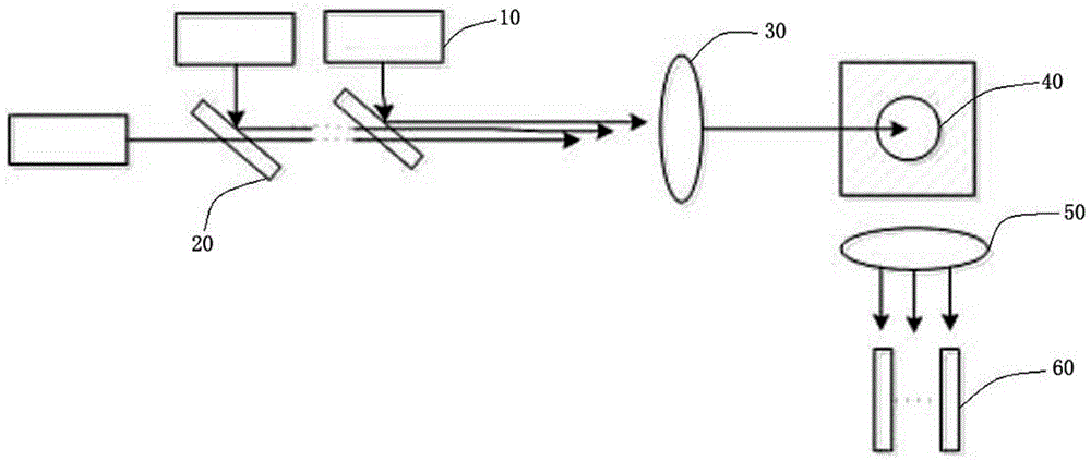
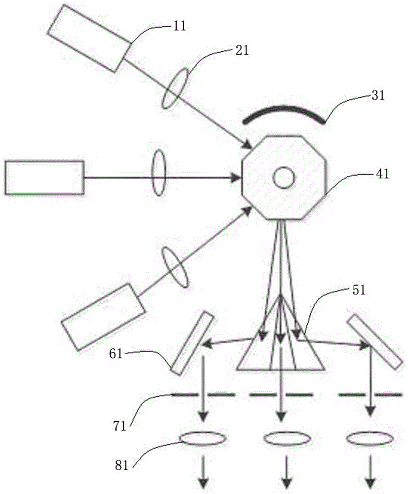
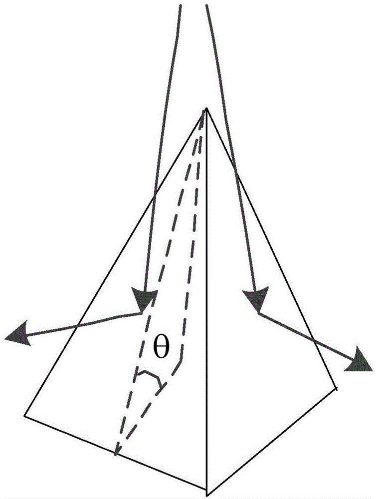
[0025] combine figure 2 Shown is an optical path device of a fluid analysis device, and the direction indicated by the arrow in the figure is the propagation path of a laser beam or a fluorescent beam. The optical path device includes a laser irradiation unit, a fluid pool 41, and a fluorescence spectroscopic unit. The fluid pool 41 is loaded with a fluid sample, and the fluid sample contains a fluorescent dye-labeled analyte. The sample is irradiated with laser light to excite the labeled fluorescence, which is split by the spectroscopic system and received by the fluorescence receiver of the fluid analysis device. The spectroscopic unit includes a pyramid for dispersing the fluorescence into multiple fluorescent beams A prism, said corner cube prism is located between the fluid cell 41 and the fluorescence receiver of the fluid analysis device. The wavelengths of the plurality of fluorescent beams are different.

[0026] The laser irradiation unit includes three lasers 11...

Embodiment 2

[0034] combine Figure 4As shown, the difference between this embodiment and Embodiment 1 is that the lasers 12 are six laser beams focused by six focusing lenses 22 into six laser beams, and the six laser beams are located on both sides of the first reflector 32 respectively. The six incident surfaces of the corner cube are incident, and the corner cube prism is a hexagonal pyramid corner cube prism 52 . The apex of the hexagonal pyramidal corner cube prism 52 is arranged facing the exit surface of the fluid pool 42 , and has six sides facing the fluid pool 41 and a bottom surface facing away from the fluid pool 42 . The fluorescent light excited by the focused light spot is projected to the hexagonal pyramidal corner cube prism 52 through the first reflector 32 , and six fluorescent beams with different wavelengths are formed after being split by six sides. The six side surfaces of the hexagonal pyramidal corner cube prism 52 are respectively provided with a second reflecto...


PUM


Abstract

The invention discloses a light path device of fluid analysis equipment. The light path device comprises a laser irradiation unit, a fluid tank and a fluorescent light splitting unit, wherein a flowing fluid sample is borne in the fluid tank and contains a fluorescent dye labelled substance to be detected; the laser irradiation unit carries out laser irradiation on the fluid sample in the fluid tank and obtains the labelled fluorescent light through excitation; the fluorescent light is received by a fluorescent light receiver of the fluid analysis equipment after being split by the fluorescent light splitting unit; the fluorescent light splitting unit comprises a corner cube used for dispersing the fluorescent light into a plurality of fluorescent light beams; the corner cube is arranged between the fluid tank and the fluorescent light receiver of the fluid analysis equipment. The invention aims to provide the light path device used for the fluid analysis equipment such as flow cytometers. The light path device can reduce the light energy loss during fluorescent light splitting, improve the fluorescent light collection efficiency and enhance the capacity of processing weak signals of subsequent circuits.

Description

technical field [0001] The invention relates to an optical path device of fluid analysis equipment, in particular to an optical path device of a flow cytometer. Background technique [0002] Flow cytometer is a precision biomedical analysis instrument integrating optics, electronics, fluid mechanics, cytochemistry and computer technology, which is used for rapid quantitative analysis and sorting of cells. With the development of various technologies, flow cytometry has become an important tool for biological and medical research. Higher sensitivity, resolution and more excitation wavelengths are the goals of flow cytometer developers and researchers. combine figure 1 The schematic diagram of the optical path device structure of the flow cytometer shown in the prior art, the multiple lasers (such as 405nm, 488nm, 633nm, etc.) The beam mirror 20 implements multi-path laser synthesis, and focuses the laser beams inside the fluid pool 40 through a common focusing lens 30 . Be...

Claims


Application Information

Patent Timeline
Patent Type & Authority Applications(China)
IPC IPC(8): G01N21/01G01N21/64
Inventor 周建康陈晓阳
Owner TAICANG NENGJIAN BIOTECH
Why Eureka
Try Eureka