
A production process of rolls for high-end rail rolling mills

A production process and roll technology, which is applied in the field of roll production process for high-end rail rolling mills, can solve the problems of high rolling pressure, broken roll operation, and low rolling output, and achieve improved red hardness, hardenability, and thermal crack resistance The effect of improving performance and prolonging service life

Active Publication Date: 2016-06-01
江苏凯达重工股份有限公司
View PDF7 Cites 0 Cited by
  • Summary
  • Abstract
  • Description
  • Claims
  • Application Information

AI Technical Summary

Problems solved by technology

[0002] The rolls used in high-end rail rolling mills, especially the rolls for rolling 50Kg and 60Kg 100-meter-long rails, have large billets, high material requirements, high rolling pressure, and various rolling passes. Therefore, other materials Alloy ductile iron rolls and alloy semi-steel rolls often have a certain amount of network-shaped carbides in the matrix structure and a large hardness drop determined by the material. During the rolling operation of the rolls, the rolling output will be low due to the above factors. The surface quality is rough and not bright, and even cause accidents of broken rolls
High consumption per ton of steel rolls, high production costs, seriously affect the production efficiency and benefits of enterprises

Method used


Image

  • A production process of rolls for high-end rail rolling mills
  • A production process of rolls for high-end rail rolling mills

Examples


Embodiment 1

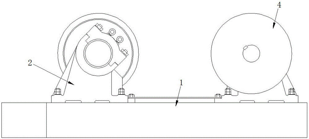
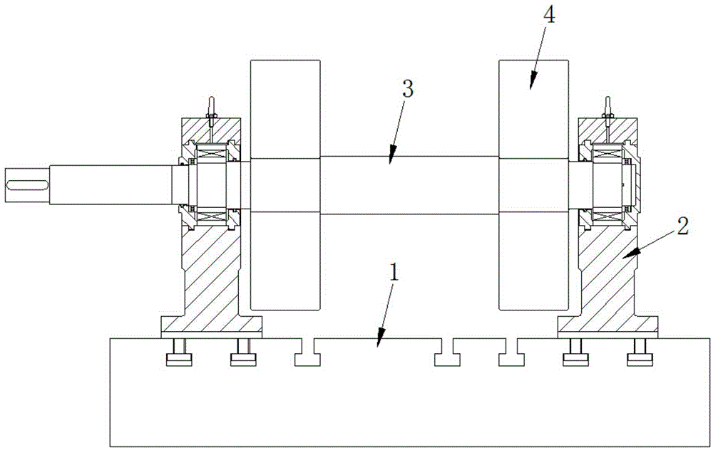
[0025] See figure 1 and figure 2 , the high-end rail rolling mill roll production process of the present embodiment comprises the following steps:

[0026] ①. Add appropriate amount of nickel, molybdenum alloy elements and trace amounts of yttrium-based heavy rare earth, vanadium, niobium, and boron elements to smelt high-purity molten iron.

[0027] Among them, the amount of yttrium-based heavy rare earth added is 2-3 kg per ton of molten iron, and the specific chemical composition of the smelted high-purity molten iron is: C: 3.00-3.50%, Si: 1.50-2.20%, Mn: 0.50-1.00 %, Cr: 0.10-0.50%, Ni: 2.50-3.50%, Mo: 0.40-1.00%, V: 0.05-0.15%, Nb: 0.05-0.15%, B: 0.05-0.20%, P≤0.05%, S ≤0.03%, Mg≥0.04%, Re: 0.02-0.03%, the rest is Fe.

[0028] ②. Using silicon calcium and rare earth magnesium spheroidization treatment, and then continuously inoculating with barium calcium inoculant.

[0029] ③. After the inoculation is completed, calm down for a while and start pouring the rolls. Af...


PUM


Abstract

The invention discloses a roller producing technology for a high-end rail rolling mill. The roller producing technology comprises the following steps that firstly, an appropriate number of nickel elements and molybdenum alloy elements and a trace of yttrium basis weight heavy rare earth elements, vanadium elements, niobium elements and boron elements are added, and high-purity molten iron is smelted; secondly, calcium silicon and rare earth magnesium balling is carried out, and continuous generating is carried out through a barium calcium nucleating agent; thirdly, still standing is carried out for a moment after generating, roller pouring is carried out, heat preservation is carried out after pouring till the temperature is equal to the normal temperature, a box is opened, and a roller workblank is obtained; fourthly, a hole is formed in the roller workblank in a coarse mode, a 30-50 mm machining margin is reserved on the single edge in the diameter direction, the roller wokblank is placed in a boiler to be processed at the high temperature, the temperature rises to A cm+30 DEG C, and heat preservation is carried out for a period of time; fifthly, the roller workblank is taken out of the boiler to be hung to a large spray quenching machine to rotate, thermal refining is carried out through water mist spray quenching, and after the temperature of the roller workblank is lowered to the range from 380 DEG C to 450 DEG C, the roller workblank is placed back to the boiler, and heat preservation is achieved. A roller produced through the technology is high in strength and good in abrasion-resisting performance, and almost no hardness difference exits between the roller surface and the bottom of a hole groove or between the roller surface and the side walls or between the roller surface and other areas.

Description

technical field [0001] The invention relates to a production process of rolls for high-end rail rolling mills. Background technique [0002] The rolls used in high-end rail rolling mills, especially the rolls for rolling 50Kg and 60Kg 100-meter-long rails, have large billets, high material requirements, high rolling pressure, and various rolling passes. Therefore, other materials Alloy ductile iron rolls and alloy semi-steel rolls often have a certain amount of network-shaped carbides in the matrix structure and a large hardness drop determined by the material. During the rolling operation of the rolls, the rolling output will be low due to the above factors. The surface quality is rough and not bright, and even cause accidents in roller breakage. High consumption per ton of steel rolls and high production costs have seriously affected the production efficiency and benefits of the enterprise. Contents of the invention [0003] The purpose of the present invention is to p...

Claims


Application Information

Patent Timeline
Patent Type & Authority Patents(China)
IPC IPC(8): B23P15/00C22C38/56C21D9/38C21D1/667B21B27/02
CPCB21B27/02B23P15/00C21D1/667C21D9/38C22C38/002C22C38/04C22C38/18C22C38/34C22C38/40C22C38/44C22C38/46C22C38/48C22C38/54C22C38/56Y02P10/20
Inventor 许健蒋志芳周国祥
Owner 江苏凯达重工股份有限公司
Learn More