Composite current collector and preparation method thereof

A current collector and optical foil technology, which is applied in the direction of hybrid capacitor current collectors, hybrid/electric double layer capacitor manufacturing, solid electrolytic capacitors, etc., can solve problems such as danger and increased production costs, and achieve low production costs, save equipment investment, Produces low-risk effects

Active Publication Date: 2014-12-10
SAMXON ELECTRONICS DONG GUAN +1
View PDF2 Cites 14 Cited by
  • Summary
  • Abstract
  • Description
  • Claims
  • Application Information

AI Technical Summary

Problems solved by technology

In this process, there is a methane atmosphere, which leads to an increase in production costs. It has h

Method used


Image

  • Composite current collector and preparation method thereof
  • Composite current collector and preparation method thereof

Examples


preparation example Construction

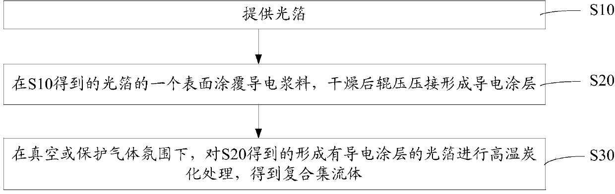
[0028] Such as figure 1 The preparation method of the composite current collector shown in one embodiment includes the following steps:

[0029] S10, providing a light foil.

[0030] The light foil can be aluminum foil, etched aluminum foil, copper foil or etched copper foil.

[0031] S20, one surface of the optical foil obtained in S10 is coated with a conductive paste, and after being dried, it is rolled and crimped to form a conductive coating.

[0032] The conductive paste is a mixture of nano-carbon material, nano-metal powder, metal catalyst, bonding resin and organic solvent.

[0033] In a preferred embodiment, the conductive paste is 5-15 parts by mass of nano-carbon material, 15-25 parts of nano-metal powder, 0.2-0.8 part of metal catalyst, 5-15 parts of bonding A mixture of resin and 80-120 parts of organic solvent.

[0034] The thickness of the conductive coating may be 1 μm˜5 μm.

[0035] The nano-carbon material can be activated carbon powder, graphene powder...

Embodiment 1

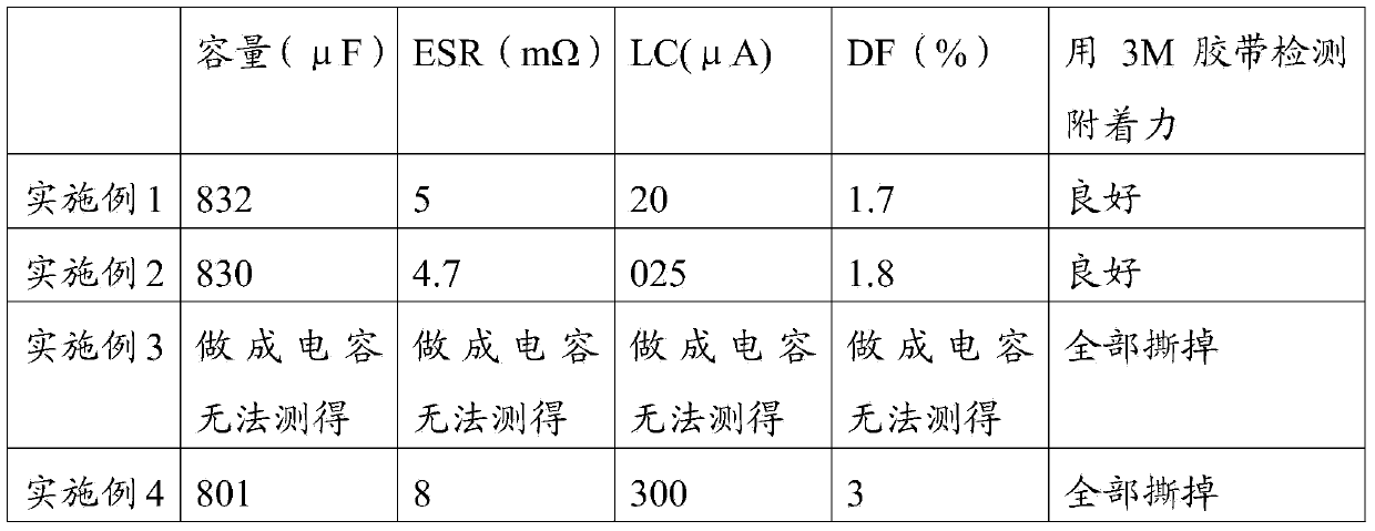
[0052] According to the number of parts by mass, 1g of conductive carbon black with an average particle diameter of 50 nanometers, 2g of aluminum powder of 100 nanometers, 1g of novolac epoxy resin, and 0.05g of nickel salicylate complex are dispersed in 10g of butanone to form a degree of dispersion Good conductive paste, coated on aluminum foil, after drying, it is rolled and crimped to form a conductive coating with a thickness of 2 μm. Finally in the vacuum furnace, 1×10 -3 Under the condition of Pa, high-temperature carbonization treatment is carried out on the aluminum foil with the conductive coating formed, the temperature of high-temperature carbonization treatment is 550° C., and the time of high-temperature carbonization treatment is 6 hours, so as to obtain the required composite current collector.

Embodiment 2

[0054] According to the number of parts by mass, the average particle diameter is 0.5g of activated carbon powder of 40 nanometers, 1.5g of nickel powder of 120 nanometers, 0.5g of novolac epoxy resin, and 0.02g of nickel salicylate complex are dispersed in 8g of butanone to form The conductive paste with good dispersion is coated on the corroded aluminum foil, and after drying, it is rolled and crimped to form a conductive coating with a thickness of 1 μm. Finally, in a vacuum furnace under a nitrogen atmosphere, the aluminum foil with the conductive coating was subjected to high-temperature carbonization treatment. The temperature of the high-temperature carbonization treatment was 450° C., and the high-temperature carbonization treatment time was 8 hours to obtain the required composite current collector.


PUM

PropertyMeasurementUnit
Thicknessaaaaaaaaaa
Particle sizeaaaaaaaaaa

Abstract

The invention discloses a composite current collector and a preparation method thereof. The method includes: coating mixture formed by nano carbon material, nano metal powder, metal catalyst, adhesive resin and organic solvent on one surface of a light foil, and rolling and pressing to form a conductive coating after drying; under a vacuum or protective gas atmosphere, performing high-temperature carbonization on the conductive coating to obtain the composite current collector. The method has the advantages that the conductive coating mixed by the nano carbon material, the nano metal powder, the metal catalyst and the adhesive resin, the adhesive resin is carbonized under catalyzing of the metal catalyst and under high temperature, and whisker-shaped carbon filaments which allow the nano metal powder and the nano carbon material to be connected, wrap the nano metal powder and the nano carbon material and is tightly combined with the light foil; no magnetic control sputtering equipment is needed, high equipment investment is avoided, no methane atmosphere is needed, and danger in production is lowered.

Description

technical field [0001] The invention relates to the field of energy storage devices, in particular to a composite current collector and a preparation method thereof. Background technique [0002] Conductive polymer solid capacitors have excellent high-frequency and low-resistance characteristics, and are widely used in various applications. With the reduction of costs, there is a tendency to gradually replace the original liquid electrolytic capacitors. However, under its superior impedance characteristics and life characteristics, solid capacitors also have obvious disadvantages compared with traditional liquid electrolytic capacitors. Its main disadvantages are: large leakage current, usually in the range of 100μA to 300μA, while the leakage of liquid capacitors is usually below 1μA, there is a big difference between the two; secondly, the withstand voltage is not high, and most of them can only be used for products below 35v at present. , Higher voltage products are diff...

Claims


Application Information

Patent Timeline
IPC IPC(8): H01G9/15H01G9/004H01G11/68H01G11/70H01G11/84H01M4/66
CPCY02E60/10
Inventor 陈宇澄徐永进韦达鸿袁美蓉
Owner SAMXON ELECTRONICS DONG GUAN
Why Eureka
Try Eureka