Organic electroluminescence device and preparation method thereof

An electroluminescence device and luminescence technology, which is applied in the direction of electric solid-state devices, semiconductor/solid-state device manufacturing, electrical components, etc., can solve problems that affect the luminous efficiency of organic electroluminescent devices, metals are easy to lose electrons, and electron transmission is hindered. , to improve photon utilization, reduce electron traps, and improve light reflection

Inactive Publication Date: 2015-02-11
OCEANS KING LIGHTING SCI&TECH CO LTD +2
View PDF0 Cites 2 Cited by
  • Summary
  • Abstract
  • Description
  • Claims
  • Application Information

AI Technical Summary

Problems solved by technology

[0002] In traditional organic electroluminescent devices, in order to match the cathode with the LUMO energy level of the organic material, the work function of the cathode is generally required to be as low as possible. If the work function is too low, it proves that the metal is easy to lose electrons, very active and stable. poor
Therefore, in the field of organic electroluminescence, metals with moderate work functions such as Ag or Al are generally used as cathodes. On the one hand, these materials have a low work function value of about 4.5eV, and their properties are relatively stable. However, they are different from organic materials. There is still a potential barrier of 1.5eV between them, which still greatly hinders the transport of electrons, thus affecting the luminous efficiency of organic electroluminescent devices.

Method used


Image

  • Organic electroluminescence device and preparation method thereof
  • Organic electroluminescence device and preparation method thereof
  • Organic electroluminescence device and preparation method thereof

Examples


preparation example Construction

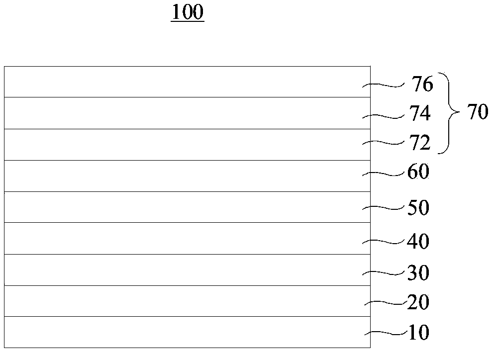
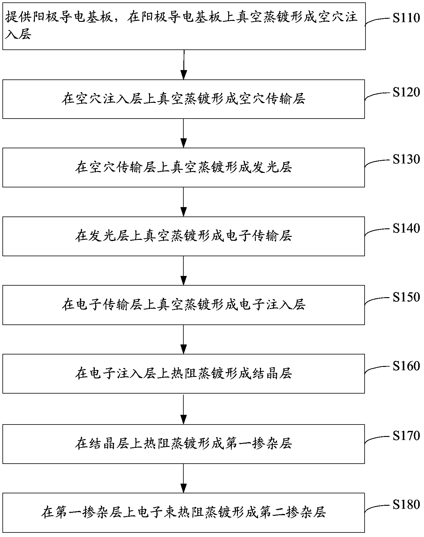
[0060] see figure 2 , a method for preparing an organic electroluminescent device according to one embodiment, comprising the following steps.

[0061] Step S110: providing an anode conductive substrate, and forming a hole injection layer by vacuum evaporation on the anode conductive substrate.

[0062] The anode conductive substrate 10 is a glass substrate with conductive patterns laminated on its surface, preferably indium tin oxide glass substrate (ITO), aluminum zinc oxide glass substrate (AZO) or indium zinc oxide glass substrate (IZO).

[0063] The glass substrate laminated with the conductive thin film is subjected to photolithography treatment, and cut into the required size to obtain the glass substrate laminated with the conductive pattern, that is, the anode conductive substrate. The conductive film is an ITO film, AZO film or IZO film.

[0064] The hole injection layer is formed by vacuum evaporation on the anode conductive substrate, and the working voltage is ...

Embodiment 1

[0101] The structure is ITO / MoO 3 / TCTA / Alq 3 / TAZ / LiF / TAZ / ReO 3 Preparation of Organic Electroluminescent Devices Based on :Cds / Ca:P7lBM

[0102] (1) To provide an anode conductive substrate, first, the glass laminated with indium tin oxide film is photolithographically processed, and cut into the required size to obtain the glass laminated with ITO conductive patterns, that is, the anode conductive substrate, expressed as ITO. The anode conductive substrate is ultrasonically washed with detergent and deionized water for 15 minutes in sequence to remove organic pollutants on the surface of the anode conductive substrate, dry and set aside;

[0103] (2) Vacuum evaporation forms a hole injection layer on the anode conductive substrate, and the working pressure is 8×10 -5 Pa, the rate of vacuum evaporation is 0.2nm / s, the material of the hole injection layer is molybdenum trioxide, and the hole injection layer is expressed as Mo0 3 , the thickness of the hole injection layer...

Embodiment 2

[0113] The structure is AZO / V 2 o 5 / TCTA / ADN / TAZ / CsF / OXD-7 / Re 2 0 7 Fabrication of Organic Electroluminescent Devices Based on :MgS / Mg:PC6lBN

[0114] (1) To provide an anode conductive substrate, first, the glass laminated with aluminum zinc oxide film is photolithographically processed, and cut into the required size to obtain the glass laminated with AZO conductive patterns, that is, the anode conductive substrate, expressed as AZO. Wash the anode conductive substrate sequentially with detergent and deionized 7K ultrasonic for 15 minutes to remove organic pollutants on the surface of the anode conductive substrate, dry and set aside;

[0115] (2) The hole injection layer is formed by vacuum evaporation on the anode conductive substrate, and the working pressure is 2×10 -3 Pa, the rate of vacuum evaporation is 0.1nm / s, the material of the hole injection layer is vanadium pentoxide, and the hole injection layer is expressed as V 2 0 5 , the thickness of the hole inject...


PUM


Abstract

The invention relates to an organic electroluminescence device and a preparation method thereof. The device comprises a cathode, wherein the cathode comprises a crystallizing layer, a first doping layer and a second doping layer and a second doping layer; the material of the crystallizing layer is 1,2,4-triazole derivatives, 2,2'-(1,3-phenyl)bi[5-(4-tertiary butyl phenyl)-1,3,4-oxadiazole], 2,9-dimethyl-4,7-diphenyl-1,10-orthophenanthrolene or 2,8-bi(diphenyl phosphine oxygroup)dibenzanthracene[b,d]thiophene; the material of the first doping layer comprises rhenium oxide and metallic sulfide; the rhenium oxide is rhenium heptoxide, rhenium dioxide, rhenium trioxide or rhenium sesquioxide; the metallic sulfide is zinc sulfide, cadmium sulfide, magnesium sulfide or copper sulphide; the material of the second doping layer comprises fullerene derivative and metal; the fullerene derivative is footballene, carbon 70, PC61BM or P71BM; the metal is magnesium, strontium, calcium or ytterbium. The device is high in luminous efficiency.

Description

technical field [0001] The invention relates to the technical field of electroluminescence, in particular to an organic electroluminescence device and a preparation method thereof. Background technique [0002] In traditional organic electroluminescent devices, in order to match the cathode with the LUMO energy level of the organic material, the work function of the cathode is generally required to be as low as possible. If the work function is too low, it proves that the metal is easy to lose electrons, very active and stable. poor. Therefore, in the field of organic electroluminescence, metals with moderate work functions such as Ag or Al are generally used as cathodes. On the one hand, these materials have a low work function value of about 4.5eV, and their properties are relatively stable. However, they are different from organic materials. There is still a potential barrier of 1.5eV between them, which still greatly hinders the transport of electrons, thus affecting th...

Claims


Application Information

Patent Timeline
Patent Type & Authority Applications(China)
IPC IPC(8): H01L51/50H01L51/54H01L51/56
CPCH10K71/166H10K50/82
Inventor 周明杰黄辉钟铁涛王平
Owner OCEANS KING LIGHTING SCI&TECH CO LTD
Why Eureka
Try Eureka