
Waste gas and waste liquid incineration system and method

A waste liquid and waste gas technology, applied in the direction of combustion method, incinerator, combustion type, etc., can solve water pollution and other problems, and achieve the effects of promoting complete combustion, increasing heat utilization rate, and reducing flue gas exhaust volume

Active Publication Date: 2015-02-18
宜兴市智博环境设备有限公司
View PDF7 Cites 12 Cited by
  • Summary
  • Abstract
  • Description
  • Claims
  • Application Information

AI Technical Summary

Problems solved by technology

The traditional landfill, surface pond, and waste stacking methods are used as final disposal methods, resulting in frequent accidents such as serious water pollution

Method used


Image

  • Waste gas and waste liquid incineration system and method
  • Waste gas and waste liquid incineration system and method
  • Waste gas and waste liquid incineration system and method

Examples


Embodiment 1

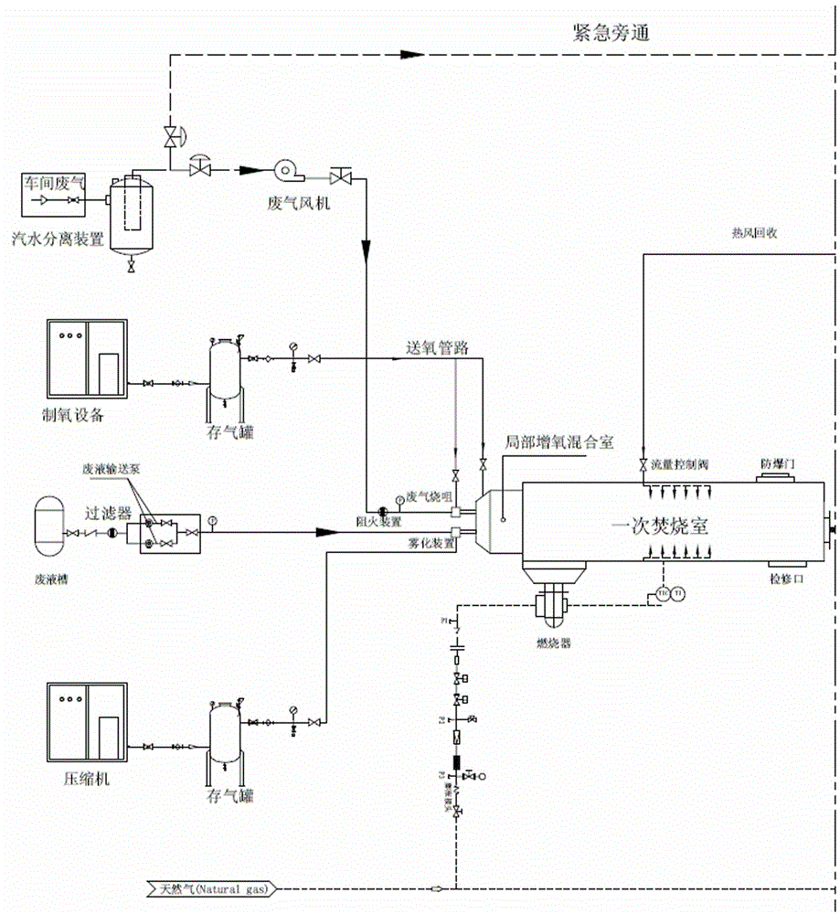
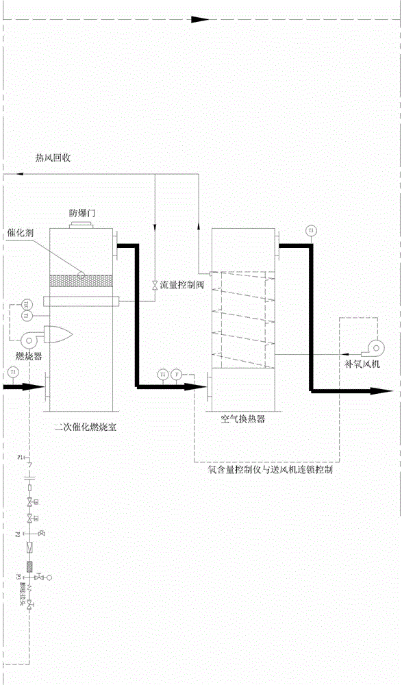
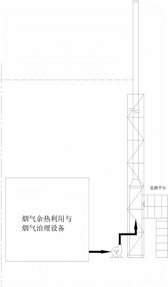
[0035] like Figure 1-2 As shown, a waste gas and waste liquid incineration system in this embodiment includes: sequentially connected oxygen production equipment, local oxygen-increased combustion mixing chamber, primary incineration chamber, secondary catalytic incineration chamber, air heat exchanger, waste heat utilization and smoke Gas purification device: Harmful waste gas or atomized waste liquid, compressed air and pure oxygen are mixed in the mixing chamber according to the set ratio and then passed into the primary incineration chamber for incineration. The waste heat utilization and flue gas purification device includes a waste heat boiler, lye washing device, mist water separator, induced draft fan and exhaust pipe connected in sequence.

[0036] The waste gas and waste liquid incineration system includes a waste liquid atomization device, which is connected with an air compression device.

[0037] The air inlet of the air heat exchanger is connected with the oxyg...

Embodiment 2

[0042] A method for waste gas and waste liquid incineration, specifically comprising the steps of:

[0043] 1) Mix waste gas or atomized waste liquid, compressed air and oxygen in the mixing chamber, wherein the ratio of oxygen to air is 1:25; among them, the waste liquid is mixed with compressed air after high-pressure atomization and then passed into the mixing chamber. The design pressure of compressed air is 0.2-0.3MPa; the ratio of compressed air used per liter of atomized waste liquid is 0.5-1Nm 3 / L; if waste gas needs to be incinerated, the waste gas will be mixed with oxygen through the waste gas nozzle and then flow into the mixing chamber. The pressure of the waste gas nozzle is designed to be 1KPa.

[0044] 2) Enter the mixed gas generated in step 1) into the primary incineration chamber for primary incineration; temperature: 750-850°C, residence time of flue gas in the primary chamber is 2 seconds;

[0045] 3) Enter the flue gas generated in step 2) into the seco...


PUM


Abstract

The invention discloses a waste gas and waste liquid incineration system. The system comprises oxygen production equipment, a local oxygen increasing, combustion and mixing chamber, a primary incineration chamber, a secondary catalytic incineration chamber, an air heat exchanger and a waste heat utilization and smoke purification device which are sequentially connected; harmful waste gas or atomized waste liquid, compressed air and pure oxygen are proportionally mixed in the mixing chamber and then are fed into the primary incineration chamber for incineration. The waste gas and waste liquid incineration system has the advantages that the content of oxygen is locally improved in the primary incineration chamber for waste gas and waste liquid, the combustion speed is accelerated, the complete combustion is facilitated, the smoke exhaust amount after combustion is reduced, and the heat utilization ratio is improved; smoke after primary incineration enters the secondary catalytic incineration chamber and reacts with catalyst, toxic gases such as ammonia and hydrogen cyanide produced after primary incineration is decomposed into N2, H2 and CO2, the problem of environmental pollution caused by smoke exhaust is solved, and the energy saving and emission reduction are facilitated.

Description

[0001] technical field [0002] The invention relates to energy-saving treatment equipment for environmental protection incineration of waste gas and waste liquid, and in particular to a waste gas and waste liquid incineration system and method. Background technique [0003] my country is an emerging country with rapid development, and its resource consumption and pollutant discharge account for an increasing proportion of the world. Developing a resource-saving and environment-friendly economy will become the main direction of national economic development in the future, and low-carbon economy will become the mainstream model of my country's future economic development. [0004] In the process of industrial production in my country, a large amount of waste water, waste gas, and waste residue are produced, most of which are treated by chemical detoxification and biodegradation. Most of the treatment methods are essentially a kind of concentration technology. The concentrate...

Claims


Application Information

Patent Timeline
Patent Type & Authority Applications(China)
IPC IPC(8): F23G7/05F23G7/07
CPCF23G7/05F23G7/07F23G2209/102F23G2209/14Y02A50/20
Inventor 王志军
Owner 宜兴市智博环境设备有限公司
Learn More