Thick-plate narrow-gap laser scanning filler wire welding method

A technology of laser scanning and welding method, which is applied in laser welding equipment, welding equipment, edge parts of workpieces, etc., can solve the problems of inability to melt the grooves on both sides of the weld, small laser focus spots, and low bridging ability. To achieve the effect of reducing heat input and heat affected zone, reducing the amount of filler metal, and reducing heat input

Inactive Publication Date: 2015-04-29
GUANGDONG PROVINCIAL INST OF WELDING TECH GUANGDONG PROVINCIAL ACADEMY OF UKRAINE
View PDF13 Cites 30 Cited by
  • Summary
  • Abstract
  • Description
  • Claims
  • Application Information

AI Technical Summary

Problems solved by technology

However, the current narrow-gap laser welding technology is limited to the size of the laser focusing head, and it is impossible to weld on deep groove welds. The weldable thickness is limited to within 20mm, and even a large groove is required, which loses the meaning of narrow-gap welding; Moreover, the laser focus spot is very

Method used


Image

  • Thick-plate narrow-gap laser scanning filler wire welding method
  • Thick-plate narrow-gap laser scanning filler wire welding method
  • Thick-plate narrow-gap laser scanning filler wire welding method

Examples


Embodiment 1

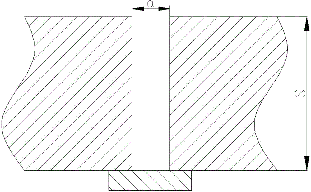
[0043] The welded thick plate is Q235 carbon steel plate with a thickness of 60mm, such as figure 2 As shown, an I-shaped groove is set between the two thick plates 4 to be welded, and the groove width a is 12 mm.

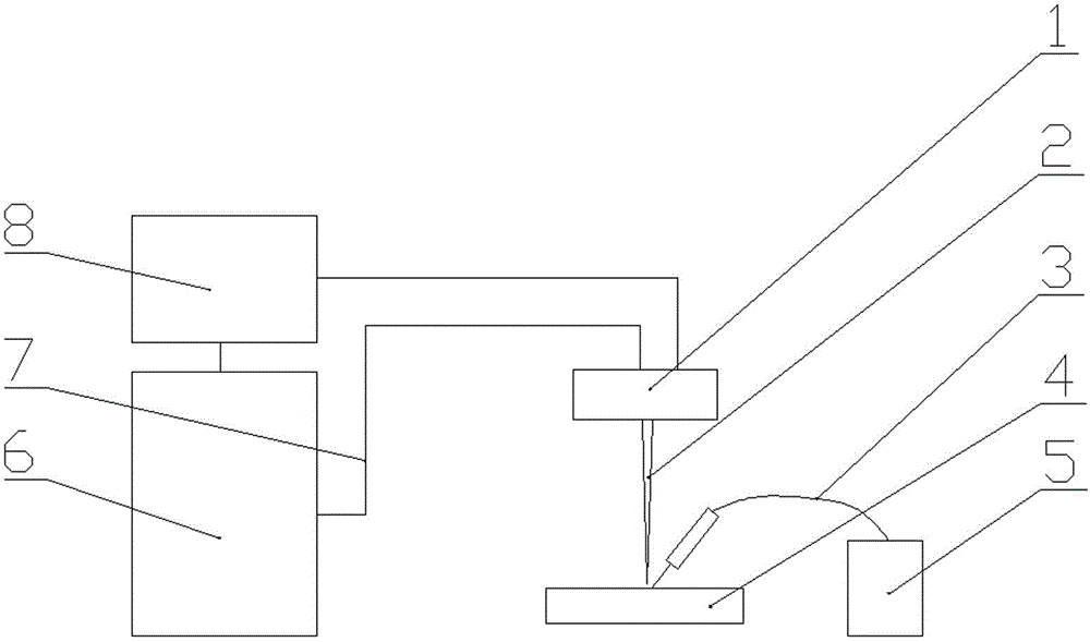
[0044] Fix the two thick plates 4 to be welded on the workbench, and at the same time put the welding head (such as Figure 6 Shown) is fixed on the ring guide rail, and the distance between the scanning galvanometer and the weld surface is adjusted.

[0045] After the preparation of the two thick plates 4 to be welded and the welding system is completed, use ER50-6 welding wire for the first welding. Set the laser power to 5000W, the defocus amount to 0, the wire feeding speed to 500mm / min, the scanning speed of the galvanometer to 100mm / s, and the scanning method to adopt Figure 7 In the form, the scanning distance is 0.4mm, and the walking speed of the welding head on the circular guide rail is 10mm / s. Protected by high-purity argon, the flow rate is 30Lmin...

Embodiment 2

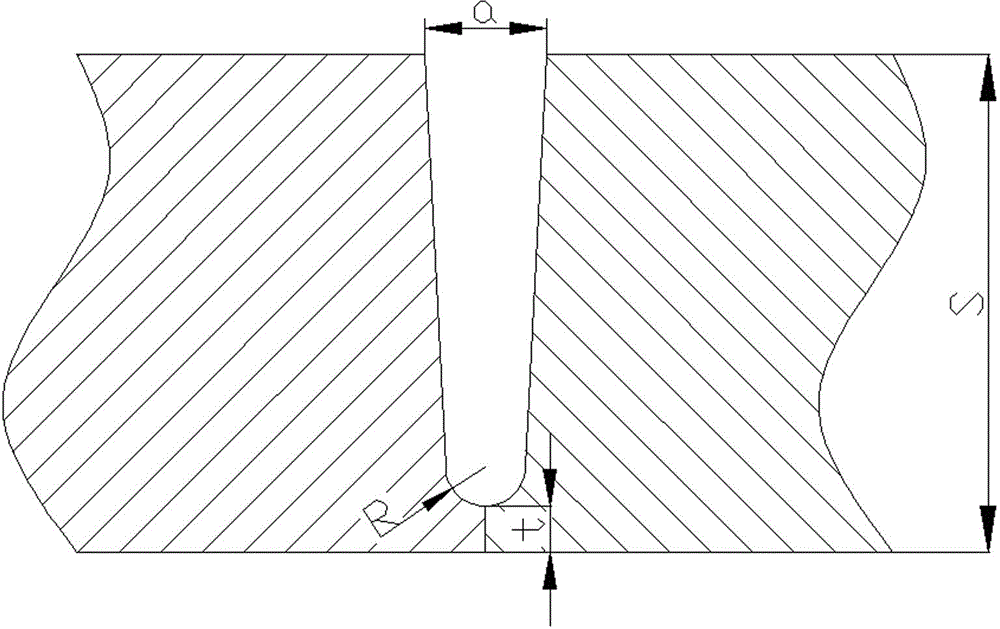
[0048] The welded thick plate is 304L stainless steel with an outer diameter of 457mm and a wall thickness of 40mm, such as image 3 As shown, for the two thick plates to be welded 4 open a deep U-shaped groove with a thick blunt edge, the blunt edge thickness t is 8mm, the groove width a is 12mm, and the arc radius R is 4.5mm.

[0049] Fix the two thick plates 4 to be welded on the clamping mechanism, and at the same time connect the welding head (such as Figure 6 Shown) is fixed on the ring guide rail, and the distance between the scanning galvanometer and the weld surface is adjusted.

[0050] After the preparation of the two thick plates 4 to be welded and the welding system is completed, the backing welding is carried out. Set the laser power to 5500W, the defocus amount to 0, and the walking speed of the welding head on the circular guide rail to be 10mm / s. Protected by high-purity argon, the flow rate is 30Lmin. During the bottom welding process, the scanning galvan...

Embodiment 3

[0053] The welded thick plate is 316L stainless steel with an outer diameter of 426mm and a wall thickness of 36mm, such as Figure 4 As shown, for the two thick plates to be welded 4, a deep V-shaped groove with a thick blunt edge is made, the thickness of the blunt edge is 10mm, the groove inclination angle α is 20°, and β is 40°.

[0054] Fix the two thick plates 4 to be welded on the clamping mechanism, and at the same time connect the welding head (such as Figure 6 Shown) is fixed on the ring guide rail, and the distance between the scanning galvanometer and the weld surface is adjusted.

[0055] After the preparation of the two thick plates 4 to be welded and the welding system is completed, the backing welding is carried out. The laser power is set to 6000W, the defocus amount is 0, and the walking speed of the welding head on the circular guide rail is 12mm / s. Protected by high-purity argon, the flow rate is 30Lmin. During the bottom welding process, the scanning g...


PUM

PropertyMeasurementUnit
Widthaaaaaaaaaa
Thicknessaaaaaaaaaa

Abstract

The invention relates to a thick-plate narrow-gap laser scanning filler wire welding method. The method comprises the steps: firstly arranging an I-type beveled edge or a deep U-type beveled edge with a thick truncated or a deep V-type beveled edge between two thick plates to be welded, transmitting laser beams to a weld seam by adopting a scanning galvanometer, carrying out the bottoming by virtue of laser self-melting welding, and then carrying out the laser scanning filler wire welding. In the filler wire welding process, the width of the beveled edge is detected in real time by adopting a visual detection system, and the deflection angle of the scanning galvanometer is further controlled, so that the laser beams can scan back and forth at two sides of the weld seam, a weld wire stretches into a gap of the beveled edge from the front of the laser beams, and the weld wire is molten by the laser which scans back and forth; the scanning galvanometer is driven by adopting a plane travel cart or an annular guide rail to move along the weld seam, and the scanning galvanometer is adjusted as the increment of welding beads, so that the laser can be focused in the plane of the weld seam to melt the weld wire. By adopting the thick-plate narrow-gap laser scanning filler wire welding method, the welding heat input can be reduced, the weld deformation can be alleviated, a thick-plate weld joint with small weld deformation and good gap side wall fusion can be obtained, and the welding efficiency and welding quality of the thick plate can be greatly improved.

Description

technical field [0001] The invention belongs to the technical field of narrow-gap welding in advanced manufacturing, and in particular relates to a narrow-gap laser scanning wire-filling welding method for thick plates, which is suitable for high-efficiency and high-quality welding of thick plates. Background technique [0002] With the development of nuclear power, marine engineering, petrochemical and other industries, the application scope of large thick plate (≥30mm) structure is increasing, and higher requirements are put forward for the deformation and mechanical properties of thick plate welded joints. [0003] Narrow gap welding technology is an advanced and efficient welding technology, which is suitable for the welding of large and thick plates and is widely used in the manufacture of heavy components. At present, the narrow-gap welding technology used in industrial production is mainly narrow-gap arc welding technology, including narrow-gap TIG, narrow-gap MIG / MAG...

Claims


Application Information

Patent Timeline
IPC IPC(8): B23K26/24B23K26/08B23K33/00B23K26/70
CPCB23K26/24B23K26/08B23K33/00
Inventor 罗子艺张宇鹏陈和兴董春林郑世达易耀勇许磊韩善果
Owner GUANGDONG PROVINCIAL INST OF WELDING TECH GUANGDONG PROVINCIAL ACADEMY OF UKRAINE
Why Eureka
Try Eureka