Optical fiber F-P multifunctional sensor based on microporous optical reflection diaphragm

An optical reflection, F-P technology, applied in the direction of using optical devices to transmit sensing components, instruments, using wave/particle radiation, etc., can solve the problems that are not conducive to miniaturized sensors, complicated operation methods, and excessive volume, so as to avoid tearing Crack and damage, fast response rate, and simplified structure

Active Publication Date: 2015-05-06
HARBIN INST OF TECH SHENZHEN GRADUATE SCHOOL
View PDF7 Cites 41 Cited by
  • Summary
  • Abstract
  • Description
  • Claims
  • Application Information

AI Technical Summary

Problems solved by technology

But its disadvantage is that the method of laser micromachining is complicated and the cost is high.
Compared w

Method used


Image

  • Optical fiber F-P multifunctional sensor based on microporous optical reflection diaphragm
  • Optical fiber F-P multifunctional sensor based on microporous optical reflection diaphragm
  • Optical fiber F-P multifunctional sensor based on microporous optical reflection diaphragm

Examples


specific Embodiment 1

[0037] as attached Figure 4 As shown, the sensor 6 of the present invention is connected to the b port of the circulator 7, the broadband light source is connected to the a port of the circulator 7, and the spectrum analyzer is connected to the c port of the circulator 7. The sensing part of the sensor is placed in the liquid, and by measuring the changes in the reflection spectrum on the spectrometer, the corresponding changes in the refractive index of the liquid can be demodulated.

specific Embodiment 2

[0038] as attached Figure 5 As shown, the sensor 6 of the present invention is connected to the b port of the circulator 7, the broadband light source is connected to the a port of the circulator 7, and the spectrum analyzer is connected to the c port of the circulator 7. The sensing part of the sensor is placed in the humidity generator, and the change of the corresponding air humidity can be adjusted by measuring the change of the reflection spectrum on the spectrometer.

specific Embodiment 3

[0039] as attached Image 6 As shown, the sensor 6 of the present invention is connected to the b port of the circulator 7, the tunable laser light source is connected to the a port of the circulator 7, the photodetector 8 is connected to the c port of the circulator 7, and the signal amplified by the signal amplifier 10 The electrical signal is detected by an oscilloscope. The sensor is placed in water, and the ultrasonic signal is generated by driving the ultrasonic transducer 9 (such as piezoelectric ceramic PZT) through the signal generator. When the external ultrasonic wave acts on the sensor, it will cause the deformation of the optical emission diaphragm (depression or protrusion), which will further cause the change of the effective optical path of the FP interference cavity, and finally manifest as the change of the interference pattern of the reflection spectrum, thereby demodulating the detected Ultrasonic information, the ultrasonic signal finally measured by the ...


PUM

PropertyMeasurementUnit
Thicknessaaaaaaaaaa

Abstract

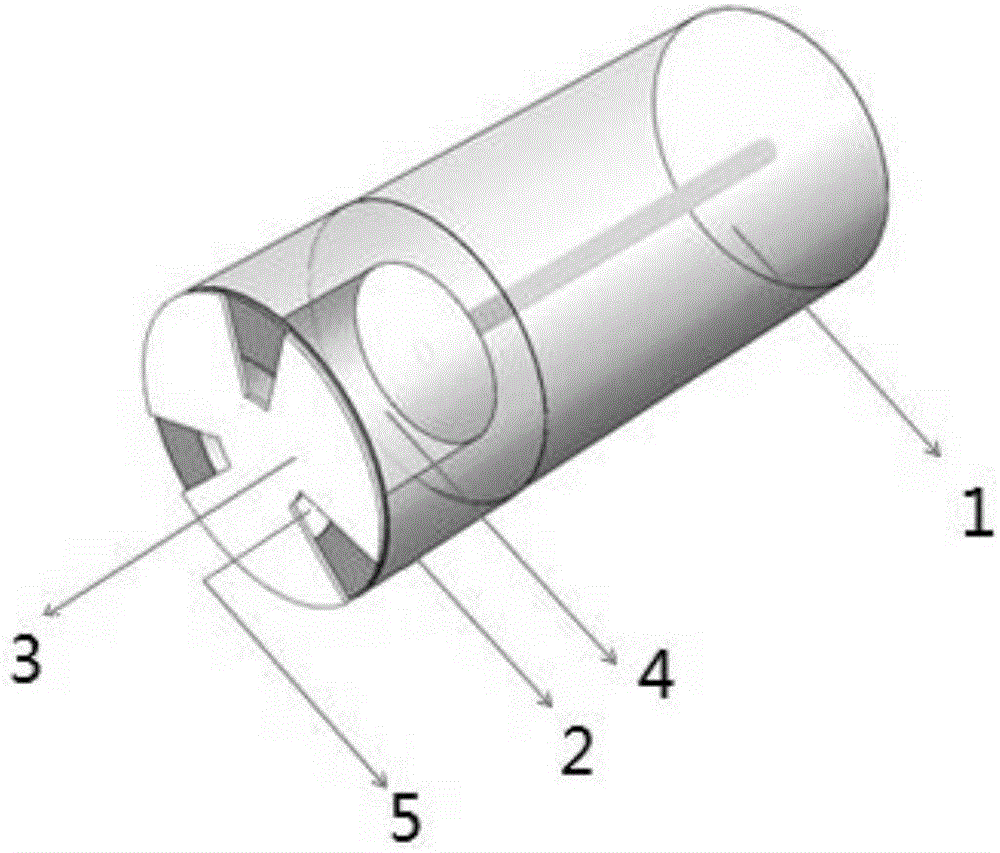
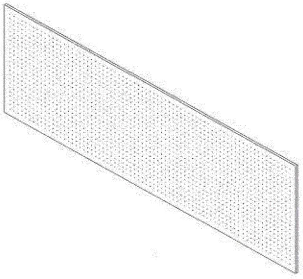
The invention provides an optical fiber F-P multifunctional sensor based on a microporous optical reflection diaphragm. The optical fiber F-P multifunctional sensor based on the microporous optical reflection diaphragm is characterized in that the design of an F-P cavity structure formed by sequentially connecting a single-die optical fiber, an optical capillary tube and the microporous optical reflection diaphragm and a special microporous optical reflection diaphragm structure is adopted to develop a built-in optical fiber F-P multifunctional sensor which can highly sensitively detecting liquid refractive index, air humidity and ultrasound under common air pressure and external high pressure conditions. The sensor has a micro size, is simple in structure, integrated, high in sensitivity, fast to respond, high in resistance to electromagnetic interference, applicable to the fields of environmental monitoring, and biochemical detection and ultrasonic detection, has a good market prospect, and is high in market value.

Description

technical field [0001] The invention relates to the technical field of optical fiber sensing, in particular to an optical fiber Fabry-Perot F-P sensor. Background technique [0002] With the rapid development of science and technology, people began to pursue the miniaturization, light weight and adaptability of sensors to harsh environments. Therefore, fiber optic sensors have become a research hotspot in recent years due to their advantages of anti-electromagnetic interference, corrosion resistance, easy reuse, high sensitivity, large measurement range, and compact structure. Commonly used optical fiber sensors mainly include: sensors based on Mach-Zehnder interferometers, sensors based on Fabry-Perot interferometers, sensors based on Sagnac interferometers, and sensors based on fiber gratings. Among them, the sensor based on the Fabry-Perot (F-P) interferometer is one of the fiber optic sensors with the longest application history, the most skilled technology and the most...

Claims


Application Information

Patent Timeline
IPC IPC(8): G01D5/353G01H9/00G01N21/45
Inventor 田佳峻全明冉李苑姚勇
Owner HARBIN INST OF TECH SHENZHEN GRADUATE SCHOOL
Why Eureka
Try Eureka