Production method of nuclear fuel clad element

A technology for cladding elements and nuclear fuels, which is applied in the field of preparation of ceramic cladding tubes for nuclear fuels, can solve problems such as lack of protection, achieve simple and easy methods, good mechanical properties and thermal conductivity, and overcome the effects of difficult processing.

Active Publication Date: 2015-05-20
NINGBO INST OF MATERIALS TECH & ENG CHINESE ACADEMY OF SCI
View PDF2 Cites 27 Cited by
  • Summary
  • Abstract
  • Description
  • Claims
  • Application Information

AI Technical Summary

Problems solved by technology

Unlike traditional air, aqueous solution, etc. oxidation, in the molten fluoride salt environment,

Method used


Image

  • Production method of nuclear fuel clad element
  • Production method of nuclear fuel clad element
  • Production method of nuclear fuel clad element

Examples


Embodiment 1

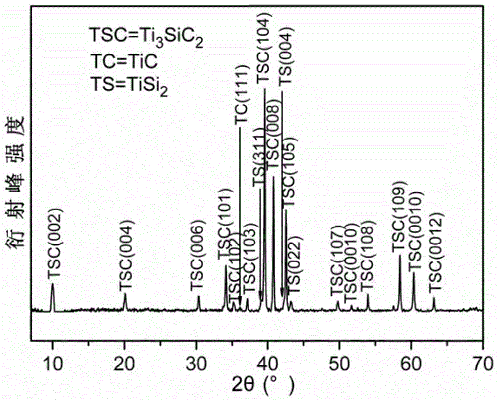
[0051] In this example, using Ti 3 SiC 2 Materials for the preparation of nuclear fuel cladding tubes.

[0052] First to commercial Ti 3 SiC 2 The bulk ceramic materials were subjected to the corrosion resistance test of molten fluorine salts.

[0053] The commercial Ti 3 SiC 2 The bulk ceramic material is prepared by powder sintering method, specifically: Weigh an appropriate amount of commercial Ti 3 SiC 2 Powder, the Ti 3 SiC 2 The powder is put into a graphite mold and pressurized in one direction to form a green body, and then put into a spark plasma sintering (SPS) furnace, heated to 1200°C in a vacuum state, and a pressure of 40MPa is applied, and the holding time is 5min.

[0054] For the Ti prepared above 3 SiC 2 The phase of the bulk material is measured and analyzed, and its XRD spectrum is as follows figure 1 As shown, it can be seen that the bulk material has high purity and low impurity content.

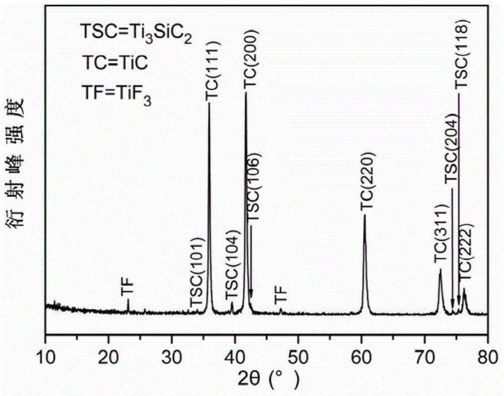
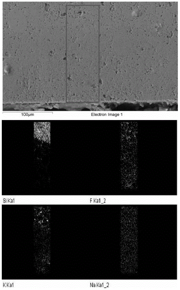
[0055] The Ti 3 SiC 2 The test method for the corro...

Embodiment 2

[0071] In this embodiment, first for Ti 3 SiC 2 -10wt% SiC composite bulk material was tested for corrosion resistance to molten fluorine salts.

[0072] The composite material is Ti 3 SiC 2 -10wt% SiC, the subsequent corrosion test was carried out in FLINAK molten salt at 700 °C, and the corrosion time was 8 days (192h). The specific process is as follows:

[0073] The Ti 3 SiC 2 -10wt%SiC composite bulk material with Ti 3 SiC 2 The ceramic material is used as a matrix, and SiC is used as a composite phase, and the composite phase accounts for 10wt% of the content of the matrix.

[0074] The composite block material is prepared by powder sintering method, specifically: Weigh an appropriate amount of commercial Ti 3 SiC 2 and SiC powder, mixed by ball milling, dried and put into a graphite mold, first pressurized in one direction to form a green body, and then put into a spark plasma sintering (SPS) furnace, heated to 1350°C under the protection of Ar atmosphere, and...

Embodiment 3-11

[0089] Similar to the above-mentioned Examples 1 and 2, the nuclear fuel cladding tubes were prepared by the same method in Examples 3-11 respectively, and the parameters such as raw materials, dispersants, plasticizers, binders, and sintering methods are as follows:

[0090]

[0091] Among them, SiC(f) represents silicon carbide fiber material.


PUM

PropertyMeasurementUnit
Thicknessaaaaaaaaaa

Abstract

The invention provides a production method of a nuclear fuel clad element. The method comprises the following steps: selecting an MAX phase ceramic material, silicon carbide, an MAX phase-based composite ceramic material or a silicon carbide-based composite ceramic material, processing the above ceramic material to prepare a slurry, carrying out vacuum defoaming, making a ceramic film with the thickness of 10[mu]m-10mm on a base band through a curtain coating or draw-off process, winding to make a clad element blank, drying, carrying out rubber discharging, sintering, and carrying out surface treatment to obtain the nuclear fuel clad element. The production method has the advantages of simplicity, easy implementation, low cost, overcoming of the disadvantage of difficult processing of ceramic materials, high production efficiency, short cycle and easy industrialization. When the ceramic material is a Ti3SiC2-baed ceramic material, the ceramic material can resist molten fluorine salt corrosion, and can be used as a fluorine salt fuel clad element material in a nuclear reactor, so practical demands of a thorium-based fourth generation fission reactor nuclear energy system on the structure material are met.

Description

technical field [0001] The invention relates to the field of nuclear energy key structural materials, in particular to a method for preparing a ceramic cladding tube for nuclear fuel. Background technique [0002] The energy crisis has become an important issue facing the world economic development. As an efficient, economical and clean energy, nuclear energy will be one of the important ways to solve the energy crisis. [0003] However, the development of nuclear energy also faces many problems. One of the problems is that we lack the uranium fuel used in conventional nuclear power. However, my country has abundant thorium raw materials, researches on the technical method of converting thorium into uranium, and adopts advanced molten salt reactor technology to develop a safer, cleaner, and ultimately more economical fourth-generation fission reactor nuclear energy based on thorium. System - thorium-based molten salt reactor nuclear energy system (TMSR) can better solve th...

Claims


Application Information

Patent Timeline
IPC IPC(8): C04B35/634C04B35/515C04B35/565C04B35/58G21C3/07
CPCY02E30/30
Inventor 黄庆周小兵王俊平邓启煌申璐周洁
Owner NINGBO INST OF MATERIALS TECH & ENG CHINESE ACADEMY OF SCI
Why Eureka
Try Eureka