Manufacture method of detection electrode of micro-fluidic chip and preparation of electrophoresis non-contact type conductivity detection system

A technology of microfluidic chips and detection electrodes, which is applied in the direction of measuring devices, electrochemical variables of materials, and material analysis through electromagnetic means, can solve the problems of high cost, complicated and time-consuming production process, etc., so as to reduce production cost and avoid instrument Reliance on equipment and harsh laboratory environment, easy and fast operation

Active Publication Date: 2015-07-01
温州品卓生物科技有限公司
View PDF5 Cites 16 Cited by
  • Summary
  • Abstract
  • Description
  • Claims
  • Application Information

AI Technical Summary

Problems solved by technology

[0008] In view of the high cost caused by the use of metal thin films to make non-contact conductivity detection electrodes, including the shortcomings of electrode materials, instruments and equipment, clean laboratory

Method used


Image

  • Manufacture method of detection electrode of micro-fluidic chip and preparation of electrophoresis non-contact type conductivity detection system
  • Manufacture method of detection electrode of micro-fluidic chip and preparation of electrophoresis non-contact type conductivity detection system
  • Manufacture method of detection electrode of micro-fluidic chip and preparation of electrophoresis non-contact type conductivity detection system

Examples


Embodiment 1

[0069] The specific embodiment of the present invention is the preferred embodiment of basic embodiment, specifically as follows:

[0070] The present embodiment is to make linear channel complex mold ( image 3 ). The dry film is Dupont Riston FX-925 negative dry film (Dupont, USA), the substrate is polyethylene terephthalate (PET) substrate, and the plastic sealing machine is an office plastic sealing machine (Simeile, China). It is linear, and the developer used is 0.85% (w / w) sodium carbonate solution.

[0071] First, the PET substrate was ultrasonically cleaned with ultrapure water, and dried in an oven. Then in the red light chamber, peel off the protective film on one side of the dry film and stick it to the PET substrate, put the PET substrate with the dry film into the paper protective case, and slowly pass it through the plastic sealing machine several times to make the dry film and PET Substrates fit tightly without air bubbles or wrinkles. Then cover the dry fi...

Embodiment 2

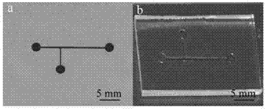
[0073] Present embodiment is to make the composite mold of T-shaped channel ( Figure 4 a), and use mold replication to obtain the corresponding PDMS microfluidic chip cover plate ( Figure 4 b). The polymer used is polydimethylsiloxane.

[0074] The specific manufacturing method of the complex mold is the same as that of Example 1, wherein the shape of the mask is T-shaped. Then mix the PDMS and Sygard 184elastomer crosslinking agent at a ratio of 10:1, pour it on the complex mold of the T-shaped channel, vacuumize it for 30 minutes, and cure it at 60°C for 2 hours after the bubbles completely disappear. Leave it at room temperature, cut out the cured PDMS with a scalpel blade, and obtain a PDMS microfluidic chip cover plate with a T-shaped concave channel.

Embodiment 3

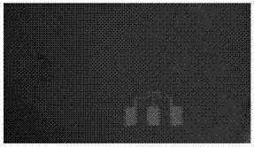
[0076] This embodiment is to make micro-droplets ( Figure 5 ).

[0077] A 2mm injection port was made at both ports of the T-shaped channel, and a syringe pump was used to drive the oil-water two-phase liquid into the channel. The flow rate of the water phase (distilled water) was controlled at 1 μL / min, and the flow rate of the oil phase (paraffin oil) was controlled at 3 μL / min. Finally, water droplets are obtained in the T-shaped channel ( Figure 4 ).

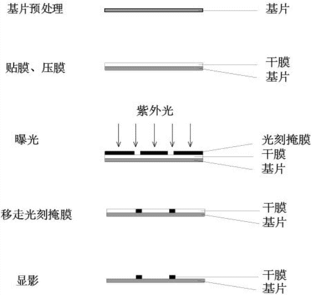
[0078] like figure 2 Shown is a schematic flow chart of making a PDMS microfluidic chip replica mold based on a photosensitive dry film. Among them, the film sticking and lamination are all completed in the red light room. The red light room is built by adding a darkroom window paper to the ordinary laboratory, and replacing the ordinary lighting with a red light.


PUM


Abstract

The invention discloses a manufacture method of a detection electrode of a micro-fluidic chip and a preparation method of an electrophoresis non-contact type conductivity detection system. The manufacture method of the compound mold of the micro-fluidic chip comprises the steps of adhering and pressing a sensitive dry film on a substrate under a non-exposed condition, exposing and developing. The preparation method of the detection electrode comprises the steps of adhering and pressing a light-sensitive material on a conductive film layer under the non-exposed condition; exposing; developing; etching; and removing the light-sensitive material. By adopting the manufacture and preparation methods, the compound mold and the corresponding micro-fluidic chip, conductive film electrode and micro-fluidic chip electrophoresis non-contact type conductivity detection system can be obtained in a quick and economical mode.

Description

technical field [0001] The invention relates to a method for manufacturing a detection electrode of a microfluidic chip based on a conductive thin film, and a method for manufacturing a microchip electrophoretic non-contact conductance detection system by combining the microfluidic chip and the conductive thin film electrode. Background technique [0002] The microfluidic chip integrates the basic operation units such as sample preparation, reaction, separation, inspection, and cell culture involved in the fields of chemistry, physics, and biology into a small chip, forming a network of microchannels, and can Controlled microfluid runs through the entire system to realize various functions in conventional chemical or biological laboratories. [0003] The principle of non-contact conductivity detection (CCD) is based on the difference in conductivity between the analyte and the background buffer solution, and quantitative detection is realized by continuously measuring the ch...

Claims


Application Information

Patent Timeline
IPC IPC(8): G01N27/30G01N27/447
Inventor 陈传品刘文芳王磊闫幸杏林航羽
Owner 温州品卓生物科技有限公司
Why Eureka
Try Eureka