Supercharge Your Innovation With Domain-Expert AI Agents!

Reclaiming method and reclaiming device of destrutive distilled oil gas of block moving bed

A recovery method and moving bed technology, which are applied in the field of massive moving bed dry distillation oil gas recovery method and its recovery device, can solve the problems of high value-added light oil loss, easy oil decomposition, pipeline blockage, etc., and achieve improved dry distillation production Oil rate, less oil and gas dust, and improved recovery

Active Publication Date: 2015-07-15
QUJING ZHONGYI FINE CHEMICAL INDUSTRY CO LTD
View PDF6 Cites 0 Cited by
  • Summary
  • Abstract
  • Description
  • Claims
  • Application Information

AI Technical Summary

Problems solved by technology

The main problem is that heavy, medium and light oils are mixed together, which increases the difficulty of oil-water separation due to the density and viscosity of the oil, especially coal tar
[0010] In addition, the light oil content in the coal gas output by the existing oil and gas recovery technology is 20-30g / Nm 3 , not only causes the loss of high value-added light oil, but also brings difficulties to the indirect heating of the heat carrier-circulating gas
Due to the indirect continuous heating of circulating gas (such as tube furnace heating), if the gas contains oil, the oil is easy to decompose and deposit carbon during the indirect heating process, resulting in pipeline blockage, making continuous heating of the heat carrier-gas impossible.

Method used


Image

  • Reclaiming method and reclaiming device of destrutive distilled oil gas of block moving bed
  • Reclaiming method and reclaiming device of destrutive distilled oil gas of block moving bed
  • Reclaiming method and reclaiming device of destrutive distilled oil gas of block moving bed

Examples


Embodiment 1

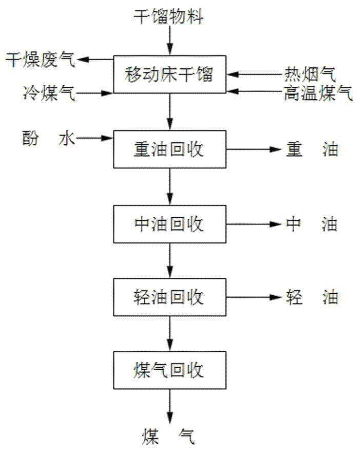
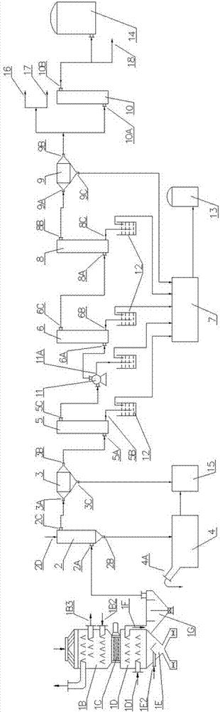
[0064] Such as figure 1 As shown, the specific steps are as follows:

[0065]1. Put the lignite lumps with a particle size of 15-18mm accounting for 83%, and the lignite lumps not greater than 25mm and greater than 18mm accounting for 17% into the drying and preheating section of the retort furnace. While moving at a slow speed, hot flue gas at 350-400°C is introduced from the lower part of the drying preheating section to directly heat the lignite block until the moisture content is less than 1% and the temperature is greater than 150°C, and 700°C is introduced from the middle or lower part of the dry distillation section. The high-temperature gas at ~750°C and the heating gas rising from the self-cooling section jointly heat and pyrolyze the lignite block step by step, and the volatile matter obtained from carbonization is collected by multiple rows of large-cavity angular boxes in the carbonization section of the carbonization furnace. Then enter the settling chamber with ...

Embodiment 2

[0071] 1. Put the oil shale blocks whose particle size is less than 80mm and not more than 75mm, accounting for 77%, and not more than 75mm and more than 70mm, accounting for 23% into the drying and preheating section of the retort furnace. The oil shale blocks are dried and preheated in the retort furnace, sealed The drying section and the retort section move slowly from top to bottom, and the hot flue gas of 300-350°C is introduced from the lower part of the drying preheating section to directly heat the oil shale block until the moisture content is less than 1% and the temperature is >110°C. The high-temperature gas of 650-700°C is fed into the middle or lower part of the retort section together with the heating gas rising from the self-cooling section to heat and pyrolyze the oil shale blocks step by step. Multiple rows of large-cavity angular boxes collect gas, and then enter the settling chamber with partitions through the oil-gas outlet through the oil-gas channel, s...

Embodiment 3

[0077] 1. Put lignite lumps with a particle size of 35-40mm accounting for 88%, and lignite lumps with a particle size of 35-40mm or less, and 12% of those larger than 35mm into the drying and preheating section of the retort furnace. Move slowly at a lower speed, introduce hot flue gas at 330-370°C from the lower part of the drying preheating section, directly heat the lignite block until the moisture content is less than 1% and the temperature is greater than 130°C, and pass in 680-370°C from the middle or lower part of the dry distillation section. The 720°C high-temperature gas and the heating gas rising from the cooling section jointly heat and pyrolyze the lignite block step by step, and the volatile matter obtained from carbonization is collected by multiple rows of large-cavity angular boxes in the carbonization section of the carbonization furnace, and then Enter the settling chamber with partitions through the oil and gas outlet through the oil and gas channel, s...


PUM

PropertyMeasurementUnit
particle sizeaaaaaaaaaa

Abstract

The invention discloses a reclaiming method and a reclaiming device of destructive distilled oil gas of a block moving bed. The method comprises the steps of destructively distilling by using a moving bed, reclaiming heavy oil, reclaiming middle distillate, reclaiming light oil and reclaiming coal gas. According to the device, the oil gas outlet of a gas retort is sequentially communicated with a direct-cooling dust collector, an electric heavy oil catcher, an intercooler, a final cooler, a light oil absorption tower, an electric light oil catcher and a desulfurizing tower; the output opening of the direct-cooling dust collector is communicated with a heavy oil settling tank, and a phenolic water inlet is formed in the upper part of the direct-cooling dust collector; a heavy oil outlet is formed in the bottom of the electric heavy oil catcher, and the intercooler, the final cooler, the light oil absorption tower and the electric light oil catcher are sequentially communicated, and an oil-water opening formed in the lower part or bottom of the electric heavy oil catcher is communicated with an oil-water separator; the coal gas opening of the electric light oil catcher is communicated with the coal gas inlet of the desulfurizing tower and / or a coal gas recycling system; and a coal gas outlet is formed in the upper part of the desulfurizing tower. The device has the characteristics of high oil collection rate, good oil product quality, subsequent processing convenience of oil products and low oil content of output coal gas.

Description

technical field [0001] The invention belongs to the technical field of energy and chemical industry, and in particular relates to a block moving bed carbonization oil gas recovery method and a recovery device thereof, which have high oil recovery rate, good oil quality, convenient subsequent processing of the oil product, and low oil content of output gas. Background technique [0002] For a long time, one of the focuses of my country's sustainable economic development has been energy. The focus of the energy issue is oil. my country's oil reserves are very limited. Facing the shortage of oil, it is becoming more and more important to find new alternative energy sources. Coal and oil shale pyrolysis technology can improve resource utilization value while reducing environmental pollution caused by coal burning, and has broad application prospects. [0003] For the recovery of massive gas heat carrier dry distillation oil and gas, direct or indirect condensation is generally ...

Claims


Application Information

Patent Timeline
Patent Type & Authority Applications(China)
IPC IPC(8): C10B47/20C10G1/00
Inventor 刘长胜罗国林
Owner QUJING ZHONGYI FINE CHEMICAL INDUSTRY CO LTD
Features
  • R&D
  • Intellectual Property
  • Life Sciences
  • Materials
  • Tech Scout
  • Unparalleled Data Quality
  • Higher Quality Content
  • 60% Fewer Hallucinations
Learn More