Application method of overhead type in-situ infrared analytic system

An in-situ infrared and analysis system technology, applied in the direction of material analysis, material analysis through optical means, and measuring devices, can solve the problems of complex reaction devices and complex structures, and achieve low manufacturing costs, simple manufacturing, and structural simple effect

Inactive Publication Date: 2015-07-15
UNIV OF SCI & TECH BEIJING
View PDF10 Cites 9 Cited by
  • Summary
  • Abstract
  • Description
  • Claims
  • Application Information

AI Technical Summary

Problems solved by technology

However, the structure of the device is complex, and it is impossible to perform spectral characterization of the reaction system with external field intervention
[0004] With the continuous innovation of catalytic reaction technology, research on low-temperature plasma, microwave, electric assist and other external fields intervening in catalytic reaction systems has been continuously reported. However, due to the relatively complicated reaction devices superimposed with external fields, there is currently no in-situ analysis system. In situ spectroscopic analysis can be achieved

Method used


Image

  • Application method of overhead type in-situ infrared analytic system
  • Application method of overhead type in-situ infrared analytic system
  • Application method of overhead type in-situ infrared analytic system

Examples


Embodiment 1

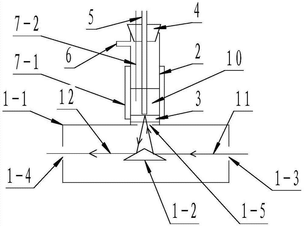
[0028] Such as figure 2 , in order to detect the reactivity of the sample catalyst 10 at different temperatures, the reaction tube 2 is made of stainless steel, the infrared window 3 is made of potassium bromide window, the sealing plug 4 and the outlet pipe 5 are removed, and the 13X molecular sieve sample catalyst 10 is packed in The bottom of the reaction tube 2 is in contact with the infrared window 3, and the sealing plug 4 is covered. At the same time, the lower nozzle of the outlet pipe 5 is inserted into the sample catalyst 10, and the upper nozzle of the outlet pipe 5 is connected to the mass spectrometer. The metal shell 1- The light exit hole 1-4 of 1 is connected to the spectrum acquisition analyzer, the outer periphery of the reaction tube 2 is provided with a heating wire 7-1, and the hole on one side of the central hole of the sealing plug 4 is provided with a thermocouple 7-2, containing NO, NH3, O2 , N2 mixed gas enters the reaction tube 2 from the inlet 6, p...

Embodiment 2

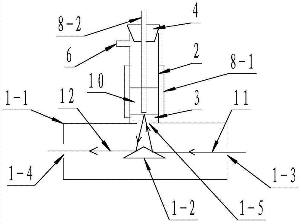
[0030] Such as image 3, in order to detect the reactivity of the sample catalyst 10 under the influence of the plasma external field, the reaction tube 2 is made of quartz glass, the infrared window 3 is made of zinc sulfide window, the sealing plug 4 is made of rubber, and the sealing plug 4 and the gas outlet pipe 5 are removed. Fill the sample catalyst 10 in the bottom of the reaction tube 2, contact the infrared window 3, cover the sealing plug 4, and insert the lower nozzle of the outlet pipe 5 into the sample catalyst 10, and connect the upper nozzle of the outlet pipe 5 to the chromatographic analysis instrument, the light exit hole 1-4 of the metal shell 1-1 is connected to the spectrum acquisition analyzer, the outer periphery of the reaction tube 2 is provided with a high-voltage electrode 8-1, and the outlet pipe 5 adopts a hollow copper tube as the low-voltage electrode 8-2; the high-voltage electrode 8 -1 and the low-voltage electrode 8-2 generate an external pla...

Embodiment 3

[0032] Such as Figure 4 , in order to detect the reactivity of the sample catalyst 10 under the influence of a microwave external field, the reaction tube 2 is made of quartz glass, the infrared window 3 is made of zinc sulfide window, the sealing plug 4 and the gas outlet pipe 5 are removed, and the sample catalyst 10 is filled in the reaction tube. The bottom of the tube 2 is in contact with the infrared window 3, and the sealing plug 4 is covered. At the same time, the lower nozzle of the outlet pipe 5 is inserted into the sample catalyst 10, and the upper nozzle of the outlet pipe 5 is connected to the chromatographic analyzer. The metal shell 1-1 The light exit hole 1-4 of the light outlet is connected to the spectrum acquisition analyzer, the microwave metal shell 9-1 is arranged outside the reaction tube 2 above the metal shell 1-1, and the nozzles of the air inlet 6 and the air outlet pipe 5 are set on the microwave metal shell 9 -1, a waveguide 9-3 is arranged betwee...


PUM


Abstract

The invention relates to an application method of an overhead type in-situ infrared analytic system. Gas enters into a reaction tube through a gas inlet and penetrates through a sample catalyst bed layer, the gas is reacted with the sample catalyst in the presence of an outer field or under the condition of no outer field, and the gas after reaction enters into a detection analyzer through a gas outlet tube; infrared light is irradiated to a reflector through a light inlet hole, enters into the sample catalyst through an infrared window after being reflected by the surface of the reflector and is reflected, refracted, scattered and absorbed for many times and returns to the surface of the reflector to form diffuse reflection infrared light; the light reflected from the surface of the reflector is irradiated to a spectra collection analyzer from a light outlet hole, and the spectra collection mode is a diffuse reflection mode; on the premise of not damaging the form of the sample catalyst, in situ spectral analysis on reaction with intervention of the outer field can be carried out, and meanwhile, the performance of the sample catalyst can be evaluated.

Description

technical field [0001] The invention relates to a spectrum measuring device, in particular to an application method of a top-mounted in-situ infrared analysis system. technical background [0002] The mechanism study of catalytic reaction is the basis of catalytic research. Diffuse reflectance Fourier transform infrared spectroscopy (DRIFTS) obtains some valuable surface reaction information by tracking and characterizing the adsorption state of the on-site reaction on the sample catalyst, and then analyzes the reaction mechanism. This technique has gained increasing attention in catalytic characterization. This characterization technique is suitable for direct determination of solid powder samples as well as surface analysis of materials. Combining the diffuse reflectance method, infrared spectroscopy and in-situ technology, the sample processing is simple, no need to press the tablet, and does not change the original shape of the sample, so it is easier to achieve under...

Claims


Application Information

Patent Timeline
IPC IPC(8): G01N21/3504G01N21/3563
Inventor 唐晓龙赵顺征易红宏高凤雨于庆君周远松王建根李倩
Owner UNIV OF SCI & TECH BEIJING
Why Eureka
Try Eureka