Permanent magnet direct-drive wind-powered generator, system and stator thereof

A technology of wind power generator and permanent magnet direct drive, which is applied in the direction of wind power generator, wind power motor combination, wind power generation, etc. It can solve the problems of withstand voltage level and life reduction, affect the service life, and can't resist, so as to prevent the insulation level from falling , the effect of prolonging the service life

Active Publication Date: 2015-07-29
XINJIANG GOLDWIND SCI & TECH
View PDF7 Cites 15 Cited by
  • Summary
  • Abstract
  • Description
  • Claims
  • Application Information

AI Technical Summary

Problems solved by technology

[0006] The wind turbine outside the nacelle running outdoors is directly soaked by rain and snow melt, and a small amount of water enters the motor from the annular gap through the rotation of the motor; when the generator stops working in wet weather, moisture enters the generator Condensation occurs inside; generators that have been shut down for a long time are prone to moisture condensation due to moisture ingress; wind turbines working in harsh environments may also suffer from accidents such as rain, snow, and water immersion (drain holes are clogged), causing moisture to enter; generator production During the process, the moisture remaining in the insulation capillary is caused by not pre-baking according to the process requirements or not drying thoroughly after dipping, etc.
[0007] (2) The reason why the generator insulation is easy to be damp
[0012] (3) Hazards caused by moisture inside the generator
They can cause deterioration of insulation performance, lead to deterioration of electrical and mechanical properties of motor insulation, reduction of residual withstand voltage level and life, and eventually lead to insulation damage
[0034] (2) All of the above are operations of ground generator sets, and the operation at an altitude of 60-100 meters, including the realization of various functions, especially the maintenance of the engine room, is usually beyond the reach of manpower and material resources, and even becomes impossible
Some good methods for ground use are inconvenient or even difficult to implement for wind turbines operating at high altitudes
[0035] (3) Relying on the above-mentioned hot air drying method alone is only a surface drying technology, which cannot solve the drying demand after the laminated layers inside the stator core are damp.
[0036] (4) The use of an open structure cannot resist the hazards of rain or snow intruding into the generator in windy and windy weather or in windy and snowy weather. The "reduced insulation level" pays for the cooling of the generator
[0037] (5) After shutdown, the humid air in the generator cavity and air gap condenses and infiltrates into the motor, which will cause the motor stator and the surface coating of the permanent magnet poles to be damp, which will affect their service life

Method used


Image

  • Permanent magnet direct-drive wind-powered generator, system and stator thereof
  • Permanent magnet direct-drive wind-powered generator, system and stator thereof
  • Permanent magnet direct-drive wind-powered generator, system and stator thereof

Examples


Embodiment 1

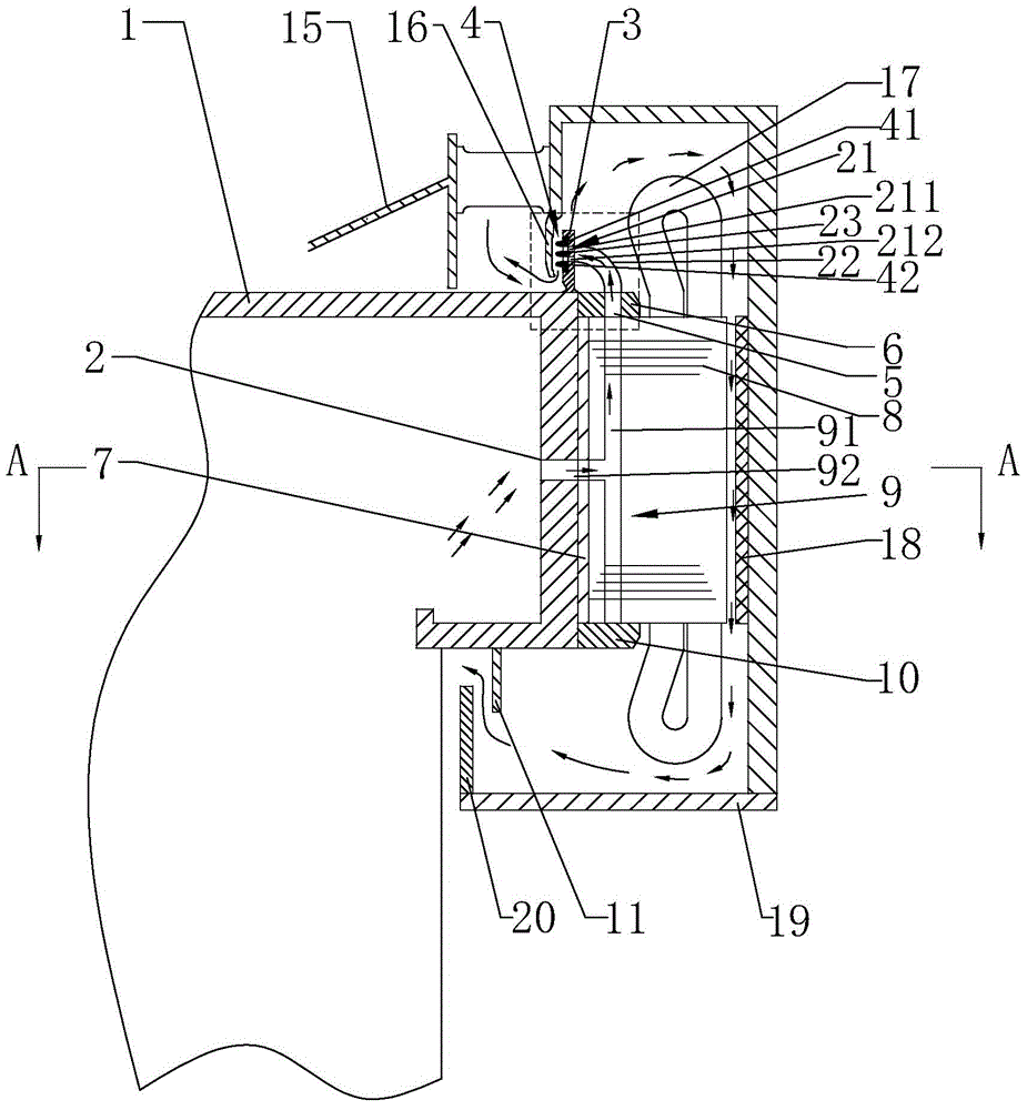
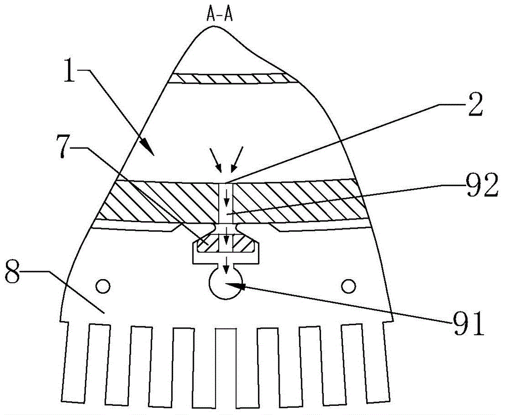
[0078] Such as figure 1 As shown, it is a schematic structural view of the stator of the permanent magnet direct drive wind power generator according to Embodiment 1 of the present invention. For ease of description, the figure 1 The upper part of the formula is defined as the propeller side (in the process of fan operation, the propeller side generally faces the upwind side), the lower part is defined as the tower side (in the process of fan operation, the tower side generally faces the downwind side), and the horizontal The direction is defined as radial direction (radial direction centering on the whole wind turbine), and the vertical direction is defined as axial direction (direction along the rotation axis of the wind turbine). In addition, the outer peripheral wall of the stator bracket 1 refers to the side wall that is in contact with or adjacent to the stator core 8 or the stamping key 7 that fixes the stator core 8 , that is, the outermost part of the stator bracket ...

Embodiment 2

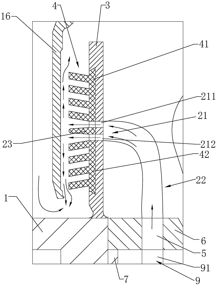
[0118] On the basis of Embodiment 1, the stator of this embodiment is also provided with a helical comb mechanism on the tower side shroud on the tower side. Specifically, such as Figure 6 and Figure 7 as shown, Figure 6 It is a schematic diagram of the stator structure of the permanent magnet direct drive wind power generator according to the second embodiment of the present invention, Figure 7 for Figure 6 A schematic diagram of the local structure. In the direction of the tower side, the stator also includes a tower side tooth pressure plate 10 and a tower side coaming plate 11. The tower side tooth pressure plate 10 is arranged on the tower side axial end face of the stator core 8. Correspondingly, the rotor bracket 15 also has an end cover. The sealing ring 20, an annular gap is formed between the end cover sealing ring 20 and the tower side coaming plate 11.

[0119] A second spiral comb mechanism 24 is also provided on the side of the paddle side shroud 3 clos...

Embodiment 3

[0124] This embodiment relates to a permanent magnet direct drive wind power generator, including a rotor and a stator described in the first or second embodiment above.

[0125] In addition, this embodiment also provides a permanent magnet direct drive wind power generator system, which includes the above wind power generator and an air source system 12 arranged inside the wind turbine, and the air source system 12 can be connected to the first air hole 2 . Wherein, as an optional implementation manner, the gas source system 12 and the components associated with the gas source system 12 are also described in the first embodiment above, and will not be repeated here.


PUM


Abstract

The invention provides a permanent magnet direct-drive wind-powered generator, system and stator thereof. The stator comprises a stator bracket, a stator iron core, a propeller side gear pressing plate and a propeller side enclosing plate; the propeller side gear pressing plate is arranged on the axial end surface of propeller side of the stator iron core; a first air hole is formed in the peripheral wall of the stator bracket; a second air hole is formed in the propeller side gear pressing plate; the stator further comprises an air channel for communicating the first air hole with the second air hole; the air channel passes through the inner part of the stator iron core; a comb teeth air feeding hole is formed in the propeller side enclosing plate and is connected with the second air hole through an air guide tube; a first spiral comb teeth structure is annular in the whole appearance and is communicated with the comb teeth air feeding hole is arranged on the propeller side enclosing plate; first spiral comb teeth are positioned in annular gaps formed by the propeller side enclosing plate and a rotor sealing ring. According to the technical scheme, the rotor has the advantage that the multi-phase airflow sealing can be performed for the annular gap between the propeller side enclosing plate and the rotor sealing ring.

Description

technical field [0001] The invention relates to a permanent magnet direct drive wind power generator, a system and a stator thereof, and belongs to the technical field of wind power. Background technique [0002] In the prior art, the open type permanent magnet direct drive external rotor wind turbine relies on natural air cooling, and the open structure is conducive to natural ventilation and heat exchange, which helps to use permanent magnet materials for the magnetic poles to prevent the magnetic degradation after the temperature rise exceeds the standard, but the generator is usually exposed. Under extremely harsh environmental conditions (exposed to wind, frost, rain, snow, sand, salt spray, etc.). [0003] 1. Sources and hazards of moisture inside the motor in a humid environment [0004] (1) Source of moisture [0005] In a humid environment, rain and snow are more likely to enter the motor than in a normal environment. In summary, the main sources of moisture are a...

Claims


Application Information

Patent Timeline
Patent Type & Authority Applications(China)
IPC IPC(8): H02K1/18H02K1/20H02K5/10H02K9/04
CPCH02K1/182H02K1/20H02K5/10H02K9/04H02K21/22H02K7/1838F05B2240/57F05B2220/7066F05B2220/7068H02K9/26H02K1/18F03D9/25Y02E10/72F16J15/54
Inventor 马盛骏辛乳江王栋刘承前
Owner XINJIANG GOLDWIND SCI & TECH
Why Eureka
Try Eureka