
Intravascular stent

A vascular stent and tubular technology, applied in stents, medical science, and pharmaceutical devices, can solve problems such as intimal hyperplasia, high restenosis rate, and reduced vascular restenosis rate, achieving high radial support force and reducing restenosis. Stenosis rate, effect of improving treatment effect

Inactive Publication Date: 2015-08-05
SUZHOU GUJI ELECTRONICS TECH
View PDF11 Cites 1 Cited by
  • Summary
  • Abstract
  • Description
  • Claims
  • Application Information

AI Technical Summary

Problems solved by technology

However, the drug stent still exists permanently in the body. There is a big difference in mechanical properties between the stent as a foreign body and the vascular tissue, which will cause chronic damage to the blood vessel, and in the later stage will cause atrophy of the vascular media, intimal hyperplasia, and eventually lead to vascular of restenosis, thus limiting the further reduction of the rate of vascular restenosis
For children, the implantation of fixed-size vascular stents will hinder the gradual increase of blood vessels and cannot meet the needs of their growth and development
[0003] The above two interventional treatment techniques for vascular stenosis have disadvantages: the use of balloon dilation of blood vessels, although the short-term effect is better, but because of the elastic retraction of blood vessels, the later restenosis rate is very high; implanting metal stents in blood vessels, Including bare stents and drug stents, which can dilate stenotic vessels and provide a durable mechanical support, but metal stents can cause intimal damage during the expansion process, induce vascular intimal hyperplasia and lead to restenosis
However, the drug release rate of the drug coating is uncontrollable, the drug loading is limited, and the therapeutic effect is not obvious

Method used


Image

  • Intravascular stent
  • Intravascular stent

Examples


Embodiment Construction

[0018] In order for examiners to better understand the technical features, technical contents and technical effects of the present invention, the accompanying drawings of the present invention will now be described in more detail in conjunction with the embodiments. However, the drawings shown are only for better illustration of the technical solution of the present invention, not the true scale and optimal configuration of the present invention, so the examiner is requested not to limit the rights of the present invention based on the proportion and configuration of the drawings Claim scope.

[0019] Below in conjunction with accompanying drawing and embodiment the patent of the present invention is further described.

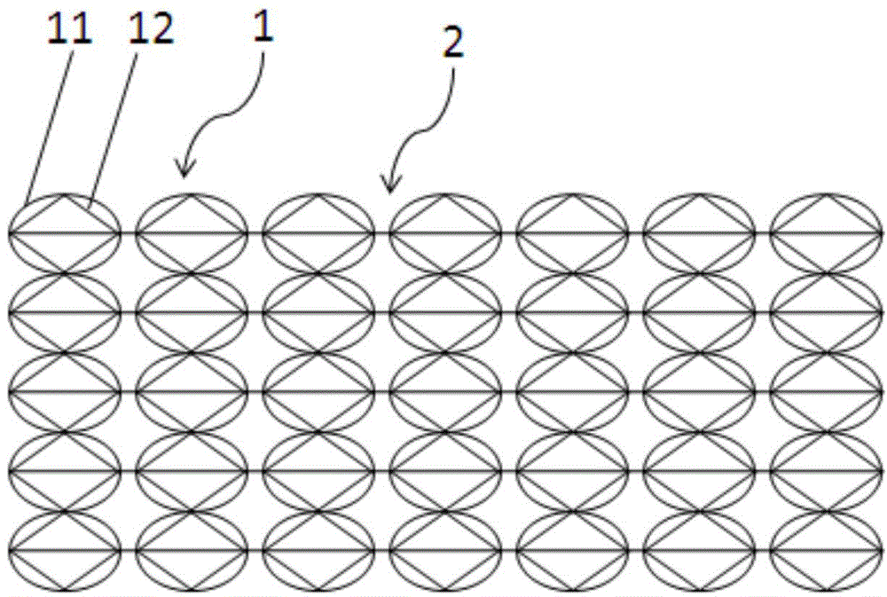
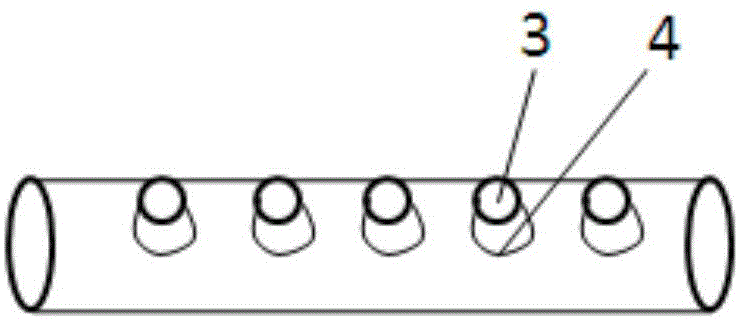
[0020] Such as Figure 1-2 As shown, the present invention provides a vascular stent, the vascular stent is tubular, including several support units 1 evenly distributed along the axial direction, and a connecting piece 2 connecting several support units 1 to...


PUM

PropertyMeasurementUnit
Lengthaaaaaaaaaa

Abstract

The invention provides an intravascular stent. The intravascular stent is in tubular shape and comprises a plurality of support units uniformly distributed in the axial direction, and a connector connecting the plurality of support units into a whole. Every support unit is composed of a flexible support part and a rigid support part connected inside the flexible support part, and the flexible support part and / or the rigid support part is a hollow tube with a plurality of pores formed in the surface; medicine carrier balloons are arranged inside the inner cavities of the hollow tubes and at the pores. The intravascular stent is characterized by avoiding injury to vascular walls and obtaining high mechanical properties and meanwhile has the advantages of being capable of carrying medicines, high in carrying capacity and convenient to medicine-release.

Description

technical field [0001] The invention relates to a blood vessel stent, which belongs to the technical field of medical instruments. Background technique [0002] In 1977, the world's first percutaneous coronary intervention (PCI) was completed in Switzerland. This operation used a balloon to dilate the stenosis of the patient's left anterior descending artery, and achieved success. However, the restenosis rate of blood vessels after balloon dilation is high, exceeding 50%. The main reason is that after the blood vessel is dilated and the external force is removed, the blood vessel will elastically recoil. In the 1980s, vascular stents widely used in coronary arteries were invented, mainly metal vascular stents made of stainless steel, cobalt-chromium alloy or nickel-titanium alloy. After these stents are implanted in the body, they can provide a durable mechanical The support avoids the elastic retraction of blood vessels and reduces the restenosis rate of diseased blood ve...

Claims


Application Information

Patent Timeline
IPC IPC(8): A61F2/82A61L31/02A61M31/00
Inventor 罗宇新
Owner SUZHOU GUJI ELECTRONICS TECH
Learn More