
A method for improving the field emission performance of carbon nanotubes by microwave hydrogen plasma treatment

A plasma and carbon nanotube technology, which is applied in the field of preparation and application of nanomaterials, can solve the problems of shortening the service life of carbon nanotube-based field emission cathodes, poor field emission stability, and reducing the field electron emission capability of cathode materials. The effect of improving field emission performance

Inactive Publication Date: 2017-02-01
TIANJIN NORMAL UNIVERSITY
View PDF6 Cites 0 Cited by
  • Summary
  • Abstract
  • Description
  • Claims
  • Application Information

AI Technical Summary

Problems solved by technology

[0003] Due to its one-dimensional characteristics, the field emission cathode based on carbon nanotubes has a smaller heat dissipation surface than graphene, a two-dimensional material, and is more susceptible to the influence of Joule heat during the field emission process, especially in the case of high current density field emission. Under certain circumstances, a part of the effective field emission points will be burned due to the large accumulation of Joule heat, which will reduce the field electron emission capability of the cathode material to a certain extent, that is, compared with the two-dimensional nanomaterials such as graphene, carbon nanotubes, Its field emission stability is poor, which will greatly shorten the service life of carbon nanotube-based field emission cathodes in practical applications

Method used


Image

  • A method for improving the field emission performance of carbon nanotubes by microwave hydrogen plasma treatment
  • A method for improving the field emission performance of carbon nanotubes by microwave hydrogen plasma treatment
  • A method for improving the field emission performance of carbon nanotubes by microwave hydrogen plasma treatment

Examples


Embodiment 1

[0040] (1) Preparation of clean silicon wafer substrate:

[0041] First, cut the silicon wafer into small pieces of 2cm×2cm, clean them with ultrasonic (50W) in deionized water, acetone and absolute ethanol for 10 minutes, and then put the silicon wafer into hydrofluoric acid with a volume ratio of 4% for 5 minutes. Minutes for clean, contamination-free substrates free of silica overlays.

[0042] (2) Deposition of iron catalyst by magnetron sputtering:

[0043] The deposition of the iron catalyst was carried out in a magnetron sputtering device (commercially available). Prior to this, the silicon single wafer was pretreated by bombardment with energetic iron ions in a metal vapor vacuum arc ion source (MEVVA source, commercially available). The iron ion energy was about 15keV, the beam current was 10 mA, and the processing time For 15 minutes, this treatment can effectively improve the bonding force between carbon nanotubes and silicon substrates; then place the silicon waf...

Embodiment 2

[0053] (1) Preparation of clean silicon wafer substrate:

[0054] First, cut the silicon wafer into small pieces of 2cm×2cm, clean them with ultrasonic (50W) in deionized water, acetone and absolute ethanol for 10 minutes, and then put the silicon wafer into hydrofluoric acid with a volume ratio of 4% for 5 minutes. Minutes for clean, contamination-free substrates free of silica overlays.

[0055] (2) Deposition of iron catalyst by magnetron sputtering:

[0056] The deposition of the iron catalyst was carried out in a magnetron sputtering device (commercially available). Prior to this, the silicon single wafer was pretreated by bombardment with energetic iron ions in a metal vapor vacuum arc ion source (MEVVA source, commercially available). The iron ion energy was about 15keV, the beam current was 10 mA, and the processing time For 15 minutes, this treatment can effectively improve the bonding force between carbon nanotubes and silicon substrates; then place the silicon waf...

Embodiment 3

[0066] (1) Preparation of clean silicon wafer substrate:

[0067] First, cut the silicon wafer into small pieces of 2cm×2cm, clean them with ultrasonic (50W) in deionized water, acetone and absolute ethanol for 10 minutes, and then put the silicon wafer into hydrofluoric acid with a volume ratio of 4% for 5 minutes. Minutes for clean, contamination-free substrates free of silica overlays.

[0068] (2) Deposition of iron catalyst by magnetron sputtering:

[0069] The deposition of the iron catalyst was carried out in a magnetron sputtering device (commercially available). Prior to this, the silicon single wafer was pretreated by bombardment with energetic iron ions in a metal vapor vacuum arc ion source (MEVVA source, commercially available). The iron ion energy was about 15keV, the beam current was 10 mA, and the processing time For 15 minutes, this treatment can effectively improve the bonding force between carbon nanotubes and silicon substrates; then place the silicon waf...


PUM

PropertyMeasurementUnit
diameteraaaaaaaaaa
diameteraaaaaaaaaa
thicknessaaaaaaaaaa

Abstract

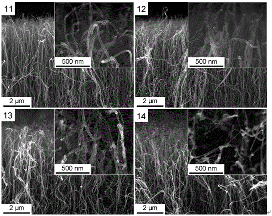
The invention discloses a method for improving field emission performance of a carbon nano tube by microwave hydrogen plasma treatment. The method mainly includes the preparation technologies of: performing bombarding pretreatment on a protreated clean silicon wafer with energy-carrying iron ions; using a conventional thermochemical vapor deposition method to prepare a carbon nano tube array on the silicon single crystal wafer; using low-power microwave hydrogen plasma to treat the carbon nano tube array; and performing heat treatment on the obtained carbon nano tube array for 3 hours at a temperature of 1273K, thereby obtaining a carbon nano tube array with improved field emission performance. Surfaces of the carbon nano tubes treated through the method enrich a large number of defects, part of the carbon nano tubes are open at the top and have smaller diameters, and when serving as field emission cathodes, the carbon nano tubes have very low opening fields and threshold fields. Heat treatment of the carbon nano tubes improves bonding of the carbon nano tubes to a substrate, thereby enabling maximum field emission current density to be substantially improved, and the method provided by the invention shows relatively high practical value in the aspect of application of large field emission current density.

Description

technical field [0001] The invention belongs to the technical field of preparation and application of nanomaterials, and relates to a method for treating carbon nanotubes with low-power microwave hydrogen plasma and performing high-temperature heat treatment on them to improve their field electron emission performance. Background technique [0002] Since their discovery in 1991, carbon nanotubes have shown good application prospects in many aspects such as photodetectors, energy storage, and transistors due to their excellent electrical and mechanical properties. In addition, the large aspect ratio and good conductivity of carbon nanotubes also make it an ideal field emission cathode material. There are potential application prospects. Field emission is the process in which electrons overcome the material surface barrier and escape into the vacuum. High-performance field electron emission is often associated with low turn-on and threshold fields, large field emission curren...

Claims


Application Information

Patent Timeline
Patent Type & Authority Patents(China)
IPC IPC(8): H01J9/02
Inventor 邓建华程国安韩阿龙程琳
Owner TIANJIN NORMAL UNIVERSITY
Learn More