Coated cutting tool and method for manufacturing the same

A cutting tool and coating technology, applied in the direction of manufacturing tools, metal material coating processes, devices for coating liquids on surfaces, etc.

Inactive Publication Date: 2015-08-26
SANDVIK INTELLECTUAL PROPERTY AB
View PDF6 Cites 8 Cited by
  • Summary
  • Abstract
  • Description
  • Claims
  • Application Information

AI Technical Summary

Problems solved by technology

However, this approach still trades off between wear and perfo

Method used


Image

  • Coated cutting tool and method for manufacturing the same
  • Coated cutting tool and method for manufacturing the same
  • Coated cutting tool and method for manufacturing the same

Examples


Embodiment 1

[0057] A coated cutting tool according to one embodiment of the present invention was manufactured. First, by pressing the powder and sintering the compact, the following cemented carbide CNMG120408-PM substrate was produced with a composition of 7.5% by weight of Co and a balance of WC, an Hc value of 13 kA / m (using Foerster Koerzimat CS1.096, Hardness according to DIN IEC 60404-7) and HV3 = 15 GPa. Prior to coating deposition, the substrate edges were rounded to about 50 μm by wet blasting.

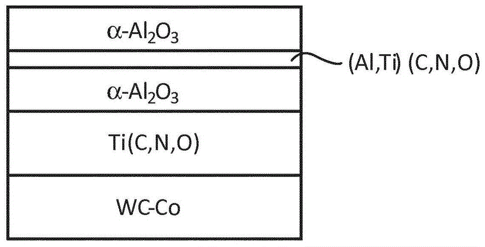
[0058] refer to figure 1 , a coating consisting of a first layer and a second layer is deposited on the substrate by CVD. The first layer is a Ti(C,N,O) layer with a total thickness of 10.3 μm consisting of the layer sequence 0.4 μm TiN, 9.1 μm MTCVD Ti(C,N), 0.2 μm HTCVD Ti(C,N) and 0.6 μm Ti(C,O) composition. The second layer is made of internal 4.5μmα-Al 2 o 3 layer, middle 2.5 μm (Al,Ti)(C,O) / TiN / Ti(C,O) layer and outer 6.8 μm α-Al 2 o 3 layered sandwich structure. Used in...

Embodiment 2

[0063] Coated cutting tools were manufactured according to Example 1, except that the wet blasting operation was different, where only the top blast was applied, see Figure 5 .

Embodiment 3

[0065] A cutting tool according to the prior art was manufactured as in Example 2 but without laser operation, comprising; CNMG120408-PM substrate with a composition of 7.5% by weight of Co and a balance of WC, 13 kA / Hc value of m (using Foerster Koerzimat CS1.096 according to DIN IEC 60404-7) and hardness of HV3 = 15GPa; and coating with 9 μm Ti(C,N) first layer and 4.5 μm α-Al 2 o 3 The second layer and Ti(C,N) colored layer. The top blasting operation removes the colored layer on the rake face.


PUM

PropertyMeasurementUnit
Thicknessaaaaaaaaaa
Total thicknessaaaaaaaaaa
Thicknessaaaaaaaaaa

Abstract

The present invention provides a coated cutting tool comprising a substrate with a rake side, a clearance side and a cutting edge, and a coating comprising a first layer and a second layer where the second layer comprises a sandwich structure consisting of an inner layer, an intermediate layer and an outer layer, wherein the inner layer is exposed through an opening in the outer layer and said opening extends over at least a portion of the width of the cutting edge. Thereby a double layer is provided in critical areas whereas a single layer is provided in other areas. Preferably the double oxide layer is an aluminum oxide layer. A method for manufacturing the coated cutting tool is also provided.

Description

technical field [0001] The present invention relates to coated cutting tools made of ceramics, cermets, cemented carbide, polycrystalline diamond, cubic boron nitride or high speed steel, suitable for turning, milling, drilling or other cuttings Forming (chip forming) machining method. Background technique [0002] Cutting tools made of ceramics, cermets or cemented carbides are often coated with hard coatings to improve wear resistance and cutting performance. The coatings are often optimized for different applications. This optimization is often based on the prevailing wear mechanisms for a particular application. For example, aluminum oxide is known to improve crater wear resistance on the rake side, and different refractory metal nitrides, carbides and carbonitrides such as titanium carbonitride are known to improve Wear resistance of the clearance side. By forming coatings comprising different layers with different properties, the wear resistance on different parts ...

Claims


Application Information

Patent Timeline
IPC IPC(8): C23C16/36B23C5/20B23B27/14B23K26/36C23C16/40C23C16/56C23C28/04
CPCB23B2224/04C23C16/56B23B27/141C23C16/36C23C28/044B23B2228/04C23C28/042B23B2224/28B23B2228/10C23C16/403B23B2224/32C23C28/04B23B2228/08B23B2224/36B23B27/14C23C16/40B05D3/06
Inventor 卡尔·比约恩曼德
Owner SANDVIK INTELLECTUAL PROPERTY AB
Why Eureka
Try Eureka