Laser cleaning device

A laser cleaning and laser technology, applied in cleaning methods and appliances, chemical instruments and methods, etc., can solve problems such as low cleaning efficiency, residual scanning fold lines, and restricted applications, and achieve the effect of improving efficiency

Active Publication Date: 2015-10-07
苏州市星科四达激光科技有限公司
View PDF6 Cites 23 Cited by
  • Summary
  • Abstract
  • Description
  • Claims
  • Application Information

AI Technical Summary

Problems solved by technology

However, laser cleaning faces a technical bottleneck problem: low cleaning efficiency, which restricts the application of this technology in large-scale automated production
The laser head generally uses a scanning galvanometer, and the scanning speed of the galvanometer is generally less than 10m / s, and the laser is processed in a point-based manner, which has low efficiency. For the cleaning of high-speed moving workpieces, there will be residual areas of scanning broken lines

Method used


Image

  • Laser cleaning device
  • Laser cleaning device
  • Laser cleaning device

Examples


Embodiment 1

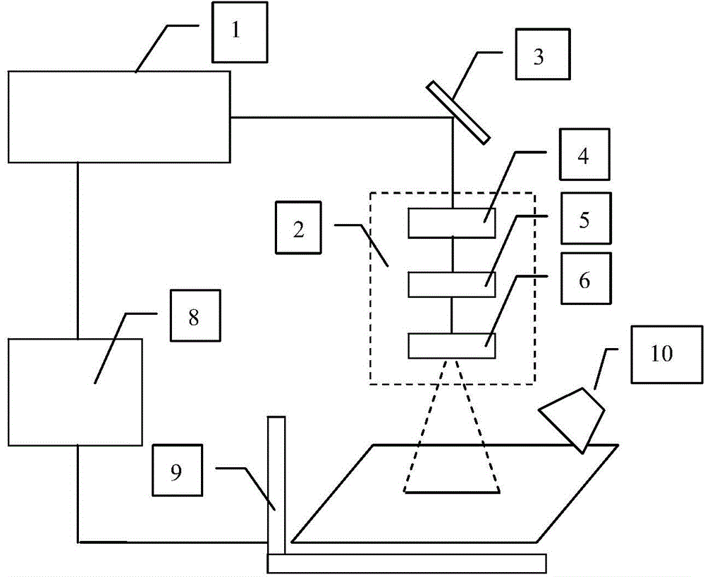
[0022] figure 1 , figure 2 Shown is a laser cleaning device of the present invention. to combine figure 1 As shown, the laser cleaning device includes a laser 1 , a spot generating mechanism 2 , a reflector 3 , a control mechanism 8 , a moving table 9 , and a dust suction mechanism 10 .

[0023] The laser 1 is a high-power continuous laser 1 for emitting laser beams. The laser 1 is one of fiber laser, disk laser, semiconductor laser or carbon dioxide laser 1, and the power of the laser 1 is greater than 500W. The power of the continuous laser has reached tens of thousands of watts, and through external modulation, it can achieve pulsed light above 10KHz, and can achieve efficient removal of large-format paint, rust, and oil.

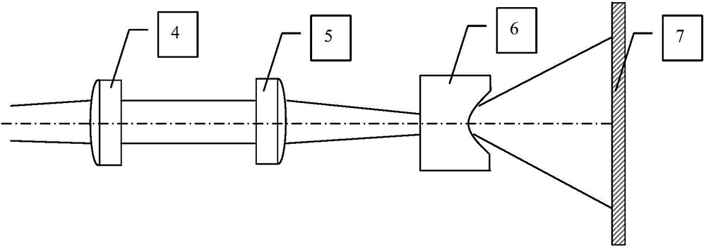
[0024] combine figure 2 As shown, the spot generating mechanism 2 includes a collimating mirror 4 and a lens group sequentially arranged in the outgoing optical path of the laser beam. Specifically in this embodiment, the lens group inc...

Embodiment 2

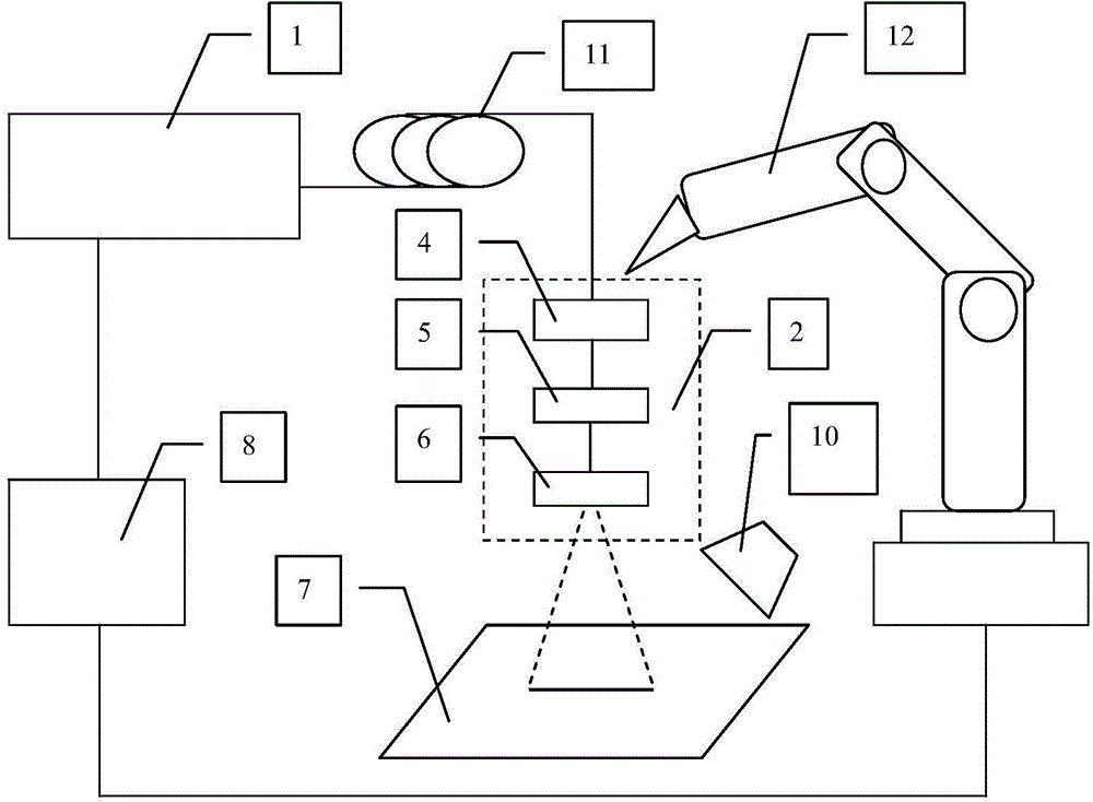
[0031] This embodiment is basically the same as Embodiment 1, combining image 3 As shown, the difference lies in the following two parts: 1. In this embodiment, a transmission fiber 11 is used to transmit the laser beam emitted by the laser 1 to the spot generating mechanism 2, instead of being reflected by the mirror 3, and the two ends of the transmission fiber 11 are respectively connected to the laser 1 and the input end of the spot generation mechanism 2; 2. In this embodiment, the robot arm 12 is used to clamp and fix the spot generation mechanism 2, and the scanning is performed by moving the spot generation mechanism 2 instead of moving the mobile workbench. The robot arm 12 and the control mechanism 8 The phase electrical connection is driven by the control mechanism 8 to drive the spot generating mechanism 2 to scan the workpiece 7 according to the preset moving speed and moving path, and the dust suction mechanism 10 is arranged above the robot arm.


PUM


Abstract

The invention provides a laser cleaning device. The device comprises a laser emitting laser beams, and a light spot generation mechanism used to perform scanning and irradiation on a to-be-cleaned workpiece. The light spot generation mechanism comprises a collimating mirror and a battery of lenses arranged in the emergent optical path of the laser beams in sequence. The battery of lenses comprises a convex cylindrical lens and a concave cylindrical lens. The convex cylindrical lens is between the collimating mirror and the concave cylindrical lens. The convex cylindrical lens and the concave cylindrical lens are arranged in an orthogonal manner. The light spot generation mechanism makes a point light source become linear beam patterns through using an optical lens system, and laser cleaning is changed to line scanning from spot scanning. On the premise of ensuring laser power density, laser cleaning efficiency is greatly improved.

Description

technical field [0001] The invention relates to a laser cleaning device. Background technique [0002] Laser cleaning is a non-contact, safe and environmentally friendly cleaning method. It has the characteristics of non-abrasive, non-contact, non-thermal effect and suitable for various materials. It avoids the environmental pollution caused by the extensive use of water-soluble cleaning agents in the traditional cleaning industry. At the same time, it also avoids the harm to human health and the risk of fire safety caused by the use of a large number of flammable, explosive and toxic cleaning agents, which meets the requirements of green manufacturing. However, laser cleaning faces a technical bottleneck problem: low cleaning efficiency, which restricts the application of this technology in large-scale automated production. [0003] The two key factors that directly affect the cleaning efficiency are the power of the laser and the scanning speed of the laser beam. At pres...

Claims


Application Information

Patent Timeline
Patent Type & Authority Applications(China)
IPC IPC(8): B08B7/00
CPCB08B7/0042
Inventor 焦俊科吴卫星
Owner 苏州市星科四达激光科技有限公司
Why Eureka
Try Eureka