Preparation method of self-aligned double-layer X-ray zone plate

A technology of X-ray and zone plates, which is applied in the field of preparation of self-aligned double-layer X-ray zone plates, can solve problems such as the difficulty of hard X-ray zone plates, and achieve low cost, high diffraction efficiency, and consistent graphics good sex effect

Inactive Publication Date: 2015-10-28
FUDAN UNIV
View PDF5 Cites 9 Cited by
  • Summary
  • Abstract
  • Description
  • Claims
  • Application Information

AI Technical Summary

Problems solved by technology

Therefore, it is difficult to prepare a hard X-ray zone plate with high resolution and high efficiency.

Method used


Image

  • Preparation method of self-aligned double-layer X-ray zone plate
  • Preparation method of self-aligned double-layer X-ray zone plate
  • Preparation method of self-aligned double-layer X-ray zone plate

Examples


Embodiment 1

[0050] Embodiment 1: Utilize self-aligned exposure technology to make double-layer high aspect ratio X-ray zone plate:

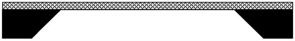
[0051] (1) Select a silicon nitride diaphragm base material with a thickness of 50nm. Deposit 5nm / 10nm Cr / Au on the substrate by physical vapor deposition as a conductive metal layer such as figure 1 shown.

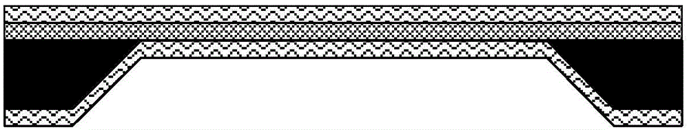
[0052] (2) Spin-coat a layer of HMDS on the front side of the substrate with a metal layer as an adhesion layer, then spin-coat a 500nm PMMA photoresist, and then do the same on the back; and bake at 180°C for 1 hour deal with. The result is as figure 2 shown.

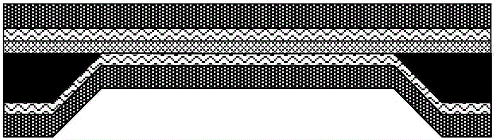
[0053] (3) Expose the sample under an electron beam exposure machine, develop the exposed sample with 1:3 MIBK and IPA for 1 minute, and develop at a temperature of 23°C; and wash in IPA for 30 seconds. The result is as image 3 shown.

[0054] (4) Electroplate Au on the surface of the developed sample using nano-electroplating technology. The electroplating conditions are: PH: 8.5, t...

Embodiment 2

[0057] Embodiment 2: Using self-aligned exposure technology to prepare a double-layer zone plate applied to hard X-rays:

[0058](1) A diaphragm of silicon nitride with a thickness of 50nm is selected as the base material. Deposit 5nm / 10nm Cr / Au on the substrate by physical vapor deposition as a conductive metal layer such as Figure 7 shown.

[0059] (2) Spin-coat a layer of HMDS on the front side of the substrate with a metal layer as an adhesion layer, then spin-coat a 500nm PMMA photoresist, and bake it at 180°C for 1 hour; then spin on the back of the sample Coat a layer of HMDS as an adhesion layer, spin-coat 500nm VUIII photoresist, and bake at 130°C for 1 minute. The result is as Figure 8 shown.

[0060] (3) Expose the sample under an electron beam exposure machine; after exposure, bake the sample at 130°C for 90s, develop it with an alkaline developer for 1 minute, wash it with deionized water and blow it dry with nitrogen before using it for 1 :3 (volume rati...


PUM


Abstract

The invention belongs to the technical field of nanostructure preparation and specifically relates to a preparation method of a self-aligned double-layer X-ray zone plate. The method comprises steps of: depositing a metallic conductive seed layer on a substrate or diaphragm; spin coating the front side and the back side of the substrate or diaphragm with photoresist, and performing exposure and development by using electron beam lithography technology in order to obtain a designed graph; obtaining a double-layer X-ray zone plate structure by using nanometer electroplating technology; dissolving the photoresist by using organic solution such as acetone or the like; etching the seed layer at the surface by means of the ionic reaction etching to obtain the double-layer X-ray zone plate. The method is stable and controllable in technological condition, good in graphic consistency, and low in cost. The X-ray zone plate prepared by the method is ultrahigh in aspect ratio, high in diffraction efficiency, and high in spatial resolution.

Description

technical field [0001] The invention belongs to the technical field of nanostructure preparation, and in particular relates to a preparation method of a self-aligned double-layer X-ray zone plate. Background technique [0002] X-rays have a short wavelength and a large penetration depth, which not only has the potential for nano-resolution imaging of thick samples, but also has a variety of imaging mechanisms (such as absorption, phase, fluorescence, etc.), and rich sources of contrast, so it can observe and analyze a variety of microscopic physics. , chemical and nanostructures, to achieve the observation of the internal three-dimensional structure of thicker substances, and has a wide range of applications in biomedicine and material science, so X-ray microscopic imaging technology has attracted more and more attention. [0003] The zone plate is an important element (lens) in the X-ray imaging system. The ring width of the zone plate determines the spatial resolution. To ...

Claims


Application Information

Patent Timeline
Patent Type & Authority Applications(China)
IPC IPC(8): G21K1/06B82Y40/00
CPCB82Y40/00G21K1/062
Inventor 陈宜方刘建朋陆冰睿李欣
Owner FUDAN UNIV
Why Eureka
Try Eureka