
Preparation method of carbon nanotube and nickel oxide composite material

A technology of composite materials and carbon nanotubes, applied in the field of nanomaterials, can solve the problem of small capacitance and achieve the effect of tight combination and wide application prospects

Active Publication Date: 2015-10-28
NORTH CHINA ELECTRIC POWER UNIV (BAODING)
View PDF8 Cites 10 Cited by
  • Summary
  • Abstract
  • Description
  • Claims
  • Application Information

AI Technical Summary

Problems solved by technology

Although carbon nanotubes have a high surface area and good electrical conductivity, they still have the disadvantage of low capacitance

Method used


Image

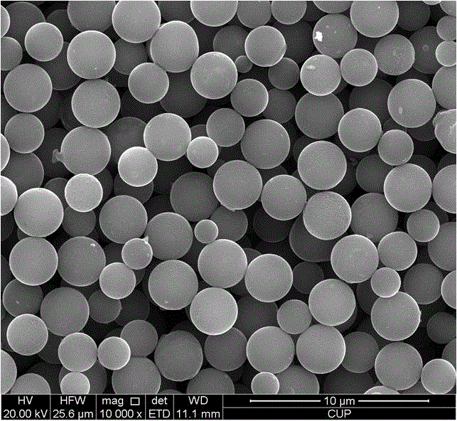
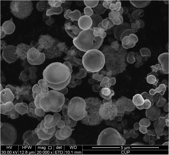
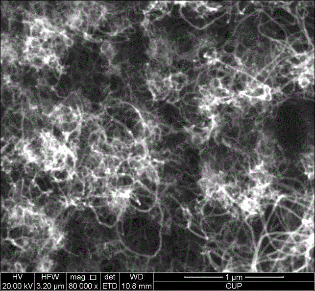
  • Preparation method of carbon nanotube and nickel oxide composite material
  • Preparation method of carbon nanotube and nickel oxide composite material
  • Preparation method of carbon nanotube and nickel oxide composite material

Examples


Embodiment 1

[0025] 1. Add 0.7g Ni(NO3) 2 ·6H 2 O, 0.9g D-glucose and 20 ml deionized water were put into a 50ml beaker, and magnetically stirred for 30 min;

[0026] 2. Transfer the solution to a polytetrafluoroethylene-lined autoclave and react at 140°C for 18 hours, then naturally cool to room temperature;

[0027] 3. Wash the obtained solid product with deionized water, suction filter until the filtrate is neutral, and dry at 50°C for 15 hours to obtain nickel hydroxide balls;

[0028] 4. Sprinkle 0.1 g of the prepared nickel hydroxide balls evenly on the silicon wafer substrate, and then place the sample in the quartz tube. Evacuate while introducing argon. Raise the temperature to 500 degrees and keep it for 3 hours to obtain the nickel oxide ball sample;

[0029] 5. Introduce hydrogen and argon at the same time, and adjust their flow ratio to 1:3. After heating up to 650°C, keep it for 0.5 hours;

[0030] 6. Raise the temperature to 750°C, introduce methane and keep it for 30 ...

Embodiment 2

[0033] 1. Add 0.9g Ni(NO3) 2 ·6H 2 O, 1.1g of D-glucose and 20 ml of deionized water were put into a 50ml beaker, and magnetically stirred for 30 min;

[0034] 2. Transfer the solution to a polytetrafluoroethylene-lined autoclave and react at 135°C for 17 hours, then naturally cool to room temperature;

[0035] 3. The obtained solid product was washed with deionized water, filtered with suction until the filtrate was neutral, and then dried at 70° C. for 24 hours. Then use a muffle furnace to calcinate at 400°C for 5 hours to obtain nano-nickel oxide balls;

[0036] 4. Sprinkle 0.25g of the prepared nickel hydroxide balls evenly on the silicon substrate, and then place the sample in the quartz tube. Vacuumize, introduce hydrogen and argon at the same time, adjust their ratio to 1:8;

[0037] 5. After heating up to 620°C, keep it for 0.5 hours;

[0038] 6. Raise the temperature to 760°C, introduce methane and keep it for 35 minutes. The ratio of the three gas sources is c...


PUM


Abstract

The invention discloses a preparation method of a carbon nanotube and nickel oxide composite material, and belongs to the technical field of nano-materials. Firstly by a hydrothermal method, a spherical structure is prepared by using a Ni(No3)26H2O and D-glucose mixing solution; the prepared nickel hydroxide of the spherical structure is placed on a silicon-based plate, argon is fed into a chemical vapor deposition system, then heating is performed to enable nickel hydroxide to be converted into nickel oxide; then hydrogen is simultaneously fed into the chemical vapor deposition system to reduce partial nickel oxide balls to nickel simple substances; and then ethene gas is fed, and carbon nanotubes grow on the surface of the partially reduced nickel oxide balls in an in-situ catalytic manner. By adopting the method, the nickel oxide and carbon nanotube composite material can be prepared simply and highly efficiently. Compared with the prior art, by adopting the method, the combination of nickel oxide and carbon tubes is more tighter, the electricity conductivity is better, the composite material is more stable, so that the performance of the composite material is effectively improved. The composite material has a wide application prospect in the field of electrochemistry devices such as a super capacitor and a lithium battery.

Description

technical field [0001] The invention belongs to the technical field of nanometer materials, and in particular relates to a preparation method of a carbon nanotube and nickel oxide composite material, which can be used as a catalyst in electrochemical devices such as supercapacitors and lithium batteries. Background technique [0002] As a new type of nanomaterial, carbon nanotubes have potential value in the fields of composite material reinforcement and catalyst field emission due to their unique hollow structure and nanometer size, as well as their high specific surface area and high electrical conductivity. Due to their high surface area and good electrical conductivity, carbon nanotubes are considered ideal materials for supercapacitors. Although carbon nanotubes have a high surface area and good electrical conductivity, they still have the disadvantage of low capacitance. Combining carbon nanotubes with transition metal oxides can effectively overcome this shortcoming....

Claims


Application Information

Patent Timeline
IPC IPC(8): H01G11/46H01G11/36H01G11/86H01M4/52H01M4/583
CPCC01B32/158H01G11/36H01G11/46H01G11/86H01M4/362H01M4/52H01M4/583Y02E60/10Y02E60/13
Inventor 李美成陈杰威王宇王帅崔鹏邵笑言
Owner NORTH CHINA ELECTRIC POWER UNIV (BAODING)
Learn More