U-shaped plate type dielectric-barrier-discharge-based low-temperature plasma reactor and reactive system

A technology of dielectric barrier discharge and low-temperature plasma, which is applied in the direction of plasma and electrical components, can solve the problems of increased operating voltage, easy damage, and irrelevant axial length of the electrode, etc., and achieve the effect of increasing the flow rate

Active Publication Date: 2015-11-11
SHANDONG ELECTRIC POWER ENG CONSULTING INST CORP
View PDF6 Cites 7 Cited by
  • Summary
  • Abstract
  • Description
  • Claims
  • Application Information

AI Technical Summary

Problems solved by technology

[0008] At present, there are mainly two kinds of dielectric barrier discharge reactors: planar electrode structure and coaxial cylindrical structure (axial air inlet), both of which have the problem of increasing the cross-sectional area of ​​gas passage in the reactor unit structure.
[0009] The main problems of the plate electrode structure are: (1) The catalytic gas flows into the DBD area perpendicular to the two plate electrodes. In the rectangular area of ​​the DBD, the gas flows through the plate electrodes in the form of laminar flow, and the electric field strength is high near the plate electrodes. There are more high-energy particles excited into the plasma state, and far away from the two flat electrodes, that is, in the middle of the rectangular area, the electric field strength is weaker, fewer high-energy particles are excited, and more low-energy particles
The breakdown discharge voltage of the flat panel reactor is proportional to the height of the discharge air gap, increasing the height of the air gap will lead to a linear increase in the operating voltage of the device, making it difficult to design and manufacture the power supply and the insulation of the system, and affect the safety of the reactor DBD
In addition, limited by the production process, it is very difficult to process, manufacture and transport flat barrier media (ceramic, quartz, etc.) with a long area and small wall thickness, and they are high in cost, low in strength, and easily damaged
[0010] The main problems of the coaxial cylindrical structure with axial air intake are: (1) The cross-sectional area of ​​the gas flow in the discharge area only depends on the annular area between the core electrode and the tube electrode, and has nothing to do with the axial length of the electrode
Limited by the cross-sectional area of ​​the gas flow, the flow of catalytic gas processed by a single reactor unit is limited
(2) In order to increase the cross-sectional area of ​​the gas flow in the cylindrical structure reactor, the only way to increase the air gap between the core electrode and the tube electrode is to increase the air gap height, which will lead to an increase in the operating voltage of the device, which will make the design and manufacture of the power supply difficult. Difficult to insulate the system
(3) The catalytic gas enters the DBD area along the axis of the reactor, and there is a laminar gas flow without disturbance. The catalytic effect of DBD is limited under low power consumption, and it is difficult to deal with the problem of large flow of catalytic gas.
In summary, the coaxial cylindrical structure with axial air intake has technical difficulties in catalytic treatment of large flow gas and enhanced DBD effect

Method used


Image

  • U-shaped plate type dielectric-barrier-discharge-based low-temperature plasma reactor and reactive system
  • U-shaped plate type dielectric-barrier-discharge-based low-temperature plasma reactor and reactive system
  • U-shaped plate type dielectric-barrier-discharge-based low-temperature plasma reactor and reactive system

Examples


Embodiment 1

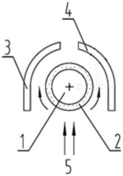
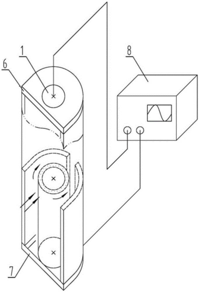
[0044] Such as figure 1 and figure 2 As shown, the core electrode rod 1 and the insulating medium 2 (quartz tube or ceramic tube) are coaxially arranged, and the insulating medium 2 is arranged close to the core electrode rod 1 . The U-shaped plate electrode cover is composed of 1 / 2U-shaped electrode plate a3 and 1 / 2U-shaped electrode plate b4, and each 1 / 2U-shaped electrode plate has a straight plate segment with a length of r and an arc segment with a radius of R. The 1 / 2U-shaped electrode plate a3 and the 1 / 2U-shaped electrode plate b4 are symmetrically arranged around the outside of the insulating medium 2, and there is a certain gap (R-r) between them and the insulating medium 2, which is the DBD gap. The gas 5 to be catalyzed enters the reactor from the U-shaped opening, and the core electrode rod 1 is located in the center of the U-shaped opening, at the front end of the reactor in the direction of gas flow. A gap is set in the middle of the U-shaped bend of the 1 / 2U...

Embodiment 2

[0048] The electrode cover 3 can also be a whole, and a gas outlet channel is provided at the arc of the whole.

Embodiment 3

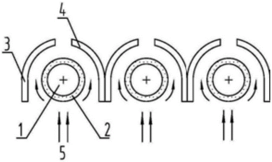
[0050] Such as image 3 and Figure 4 As shown, three reactors are arranged in parallel, and the centerlines of the core electrode rods 1 of each reactor are in the same plane. The driving power supply 8 is connected to all reactors in parallel. There can also be multiple reactors arranged in parallel, such as 3, 4, 5 and more.


PUM


Abstract

The invention relates to a U-shaped plate type dielectric-barrier-discharge-based low-temperature plasma reactor and reactive system. The reactor comprises a core electrode, a U-shaped plate electrode housing, an insulating medium and a driving power. The core electrode is installed inside the U-shaped plate electrode housing; and gas outlet channel parallel to the core electrode is arranged at the arc position of the U-shaped plate electrode housing. The insulating medium is installed between the core electrode and the U-shaped plate electrode housing. The driving power is respectively connected with the core electrode and the U-shaped plate electrode housing. Gas enters the reactor through a U-shaped opening of the U-shaped plate electrode housing; and the processed gas leaves the reactor through the gas outlet channel. According to the reactor, large-flow gas can be processed; the gas disturbance can be enhanced and the plasma catalysis can be strengthened; the mixed uniform degree of several kinds of gas can be improved; the dielectric barrier discharge (DBD) breakdown voltage and discharging power are low and the waste gas treatment cost can be lowered; and the reactor can work separately or work in a matrix arrangement mode.

Description

technical field [0001] The invention belongs to the field of low-temperature plasma catalytic treatment of industrial waste gas, and in particular relates to a U-shaped plate dielectric barrier discharge low-temperature plasma reactor and a reaction system. Background technique [0002] Plasma technology is one of the frontiers of high-tech research. Plasma is a collection of positive and negative particles (including positive ions, negative ions, electrons, free radicals and various active groups, etc.) with similar charges. A quasi-neutral non-condensed system that exhibits collective behavior is a new aggregated state other than the three states of solid, liquid, and gas, also known as the fourth state of matter. The gas itself is an electrical insulator. When the applied voltage reaches the ignition voltage of the gas, the gas molecules are broken down to generate a low-temperature plasma of a mixture including electrons, various ions, atoms and free radicals. Although ...

Claims


Application Information

Patent Timeline
Patent Type & Authority Applications(China)
IPC IPC(8): H05H1/24
Inventor 高岩高永芬栾涛张军梅张乐川张书迎苏乐
Owner SHANDONG ELECTRIC POWER ENG CONSULTING INST CORP
Why Eureka
Try Eureka