Composite optical fiber sensing system and sensing method

An optical fiber sensing system and composite technology, applied in measuring devices, instruments, measuring ultrasonic/sonic/infrasonic waves, etc., can solve the problems of inability to identify vibration events, high false alarm rate, low frequency response, etc., and achieve low noise level , low false alarm rate and high sensitivity

Active Publication Date: 2015-11-18
天津精仪精测科技有限公司
View PDF4 Cites 23 Cited by
  • Summary
  • Abstract
  • Description
  • Claims
  • Application Information

AI Technical Summary

Problems solved by technology

However, because the frequency of its transmitted pulse is limited by the length of the optical fiber, its frequency res

Method used


Image

  • Composite optical fiber sensing system and sensing method
  • Composite optical fiber sensing system and sensing method
  • Composite optical fiber sensing system and sensing method

Examples


Embodiment 1

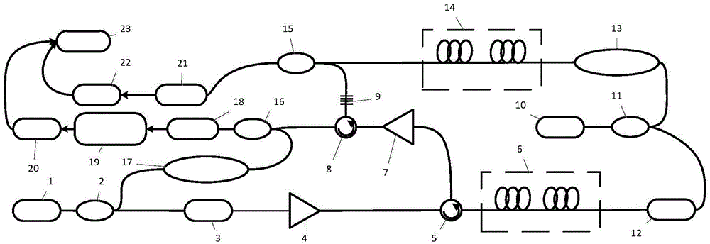
[0042] A composite optical fiber sensing system based on the principle of phase-sensitive OTDR, the principle of Mach-Zehnder interferometer, and the principle of FBG wavelength division multiplexing, including: laying a sensing optical fiber 6 in the range where vibration needs to be detected, and using the sensing optical fiber 6 As a sensor and signal transmission medium, vibration detection and monitoring are realized; an ultra-narrow linewidth laser light source 1 (linewidth hundreds of kHz) is used as a part of the light source of the phase-sensitive OTDR (optical frequency v 1 ), injecting detection light into the sensing fiber 6 in the forward direction.

[0043] Among them, the continuous probe light emitted by the ultra-narrow linewidth laser source 1 is modulated into pulsed light by an acousto-optic modulator (AOM) 3, and then amplified by the first erbium-doped fiber amplifier (EDFA) 4, and then passed through the first circulator 5 Inject the sensing fiber 6. Th...

Embodiment 2

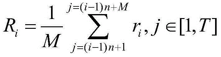
[0053] At the computer 23, a higher sampling frequency (such as 100MHz) is selected. Obtain the Rayleigh scattering signal S of the ultra-narrow linewidth laser light source 1 from the first acquisition card 20 and the second acquisition card 22 respectively 2 , and the interference detection signal S of the narrow linewidth laser source 10 1 , according to the repetition frequency of the modulation signal of the acousto-optic modulator 3, the Rayleigh scattering signal S 2 Truncate into multiple scatter traces in time order r = {r 1 ,r 2 ,r 3 ,...,r i ,...,r k}.

[0054] In order to realize the location of the vibration event, the improved moving average algorithm is used to reduce the signal noise, and the wavelet information entropy method is used to eliminate the influence of the attenuation along the sensing fiber 6 and quickly and accurately locate the location of the vibration. Specifically include the following processes:

[0055] 101: Average K scattering trac...


PUM


Abstract

The invention discloses a composite optical fiber sensing system and a sensing method. By adopting the system and the method, the same positioning precision as phase-sensitive OTDR can be achieved. Moreover, high-frequency details of vibration can be obtained, the type of vibration can be identified accurately, and the false alarm rate of the system is effectively reduced. The phase-sensitive OTDR carried out detection by using reverse Rayleigh scattered light, the intensity of reflected light is extremely low, and the light intensity power of an interferometer is high. Therefore, light signals of the phase-sensitive OTDR can be easily submerged in signals of the interferometer. By introducing a FBG, the system successfully combines light paths and separates light signals of the interferometer and a scatterometer, and the system is relatively simple in structure and low in cost. By performing an improved moving average algorithm and a wavelet information entropy algorithm on Rayleigh scattered signals of a laser light source with ultra narrow line width, the accurate position of vibration can be worked out. Interference signals of the laser light source with ultra narrow line width contain rich frequency information, and through wavelet packet decomposition on the interference signals, the type of vibration can be identified via a neural network. The rate of false alarm is reduced.

Description

technical field [0001] The invention relates to the field of optical fiber sensing, in particular to a composite optical fiber sensing system and sensing method based on the principles of Bragg grating, Mach-Zehnder interferometer and phase optical time domain reflectometer. Background technique [0002] Due to its high sensitivity, immunity to electromagnetic interference, wide detection range, and low cost, distributed optical fiber sensing systems are widely used in long-distance oil and gas pipeline monitoring, perimeter security, and building structure health monitoring. research hotspots. [0003] The Mach-Zehnder / Sagnac interferometer distributed optical fiber sensing system uses the detection of phase difference changes caused by external disturbances in the two sensing optical paths, and uses the correlation time delay estimation method for positioning, which can sense vibrations well. However, due to the difficulty of determining the time delay in the correlation ...

Claims


Application Information

Patent Timeline
IPC IPC(8): G01H9/00
Inventor 封皓施羿沙洲曾周末靳世久
Owner 天津精仪精测科技有限公司
Why Eureka
Try Eureka