Micro-fluidic chip achieving multi-index detection

A microfluidic chip, multi-index technology, applied in laboratory containers, laboratory utensils, chemical instruments and methods, etc., can solve the problem of unfavorable detection reactions, accurate control of detection results, accurate analysis of detection results, cross-contamination of reaction reagents, and sample volume. problems such as differences, to avoid reagent contamination and mutual interference, low cost and simple structure

Active Publication Date: 2015-12-23
GETEIN BIOTECH
View PDF6 Cites 30 Cited by
  • Summary
  • Abstract
  • Description
  • Claims
  • Application Information

AI Technical Summary

Problems solved by technology

Although the chip can realize the connection and isolation between the reaction cells by controlling the switch of the pneumatic microvalve, it is easy to cause cross-contamination of the reaction reagents during the sample injection flow process, and the sample needs to flow through multiple connected reaction cells after injection. The reaction pools can be fully filled, and the flow rate of the liquid in the channel is different, resulting in a large difference in the amount of samples participating in each detection reaction between the reaction pools at different positions, which is not conducive to the precise control of each detection reaction and the accurate analysis of the detection results.

Method used


Image

  • Micro-fluidic chip achieving multi-index detection
  • Micro-fluidic chip achieving multi-index detection
  • Micro-fluidic chip achieving multi-index detection

Examples


Embodiment 1

[0028] Embodiment 1: Microfluidic chip structure

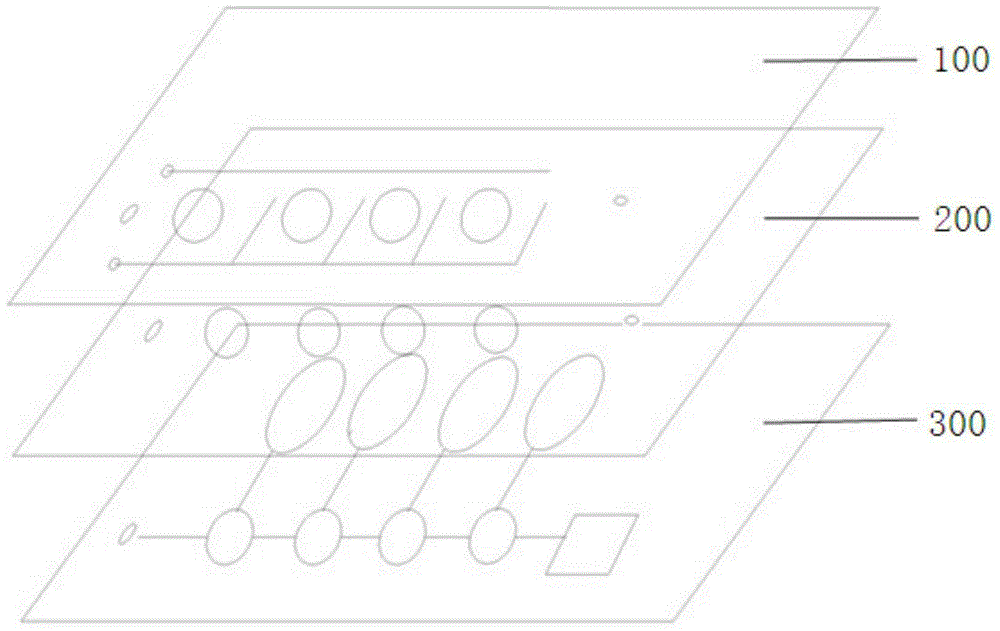
[0029] Such as figure 1 , 2 , 3, 4, and 5: A microfluidic chip for the detection of multiple biochemical indicators, which is formed by bonding and sealing chip materials with integrated microvalves, including a gas control channel layer 100, organic polymer The film 200, the microfluidic channel layer 300, in which:

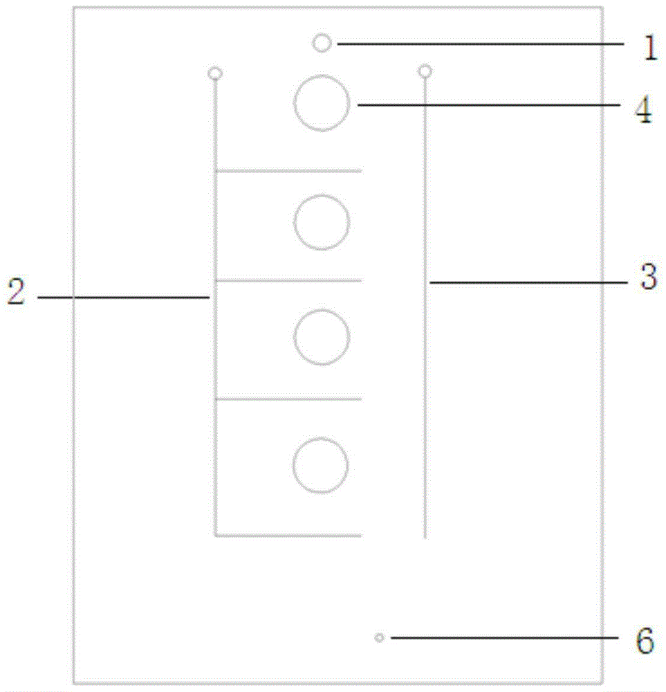
[0030] The gas control channel layer 100 is provided with a sample injection hole 1, a gas outlet 6, two pneumatic microvalves 2, 3, and the upper part of a plurality of serial sample reservoirs 4, and the upper half of the sample reservoir 4 One side is elastic film and exposed to the air;

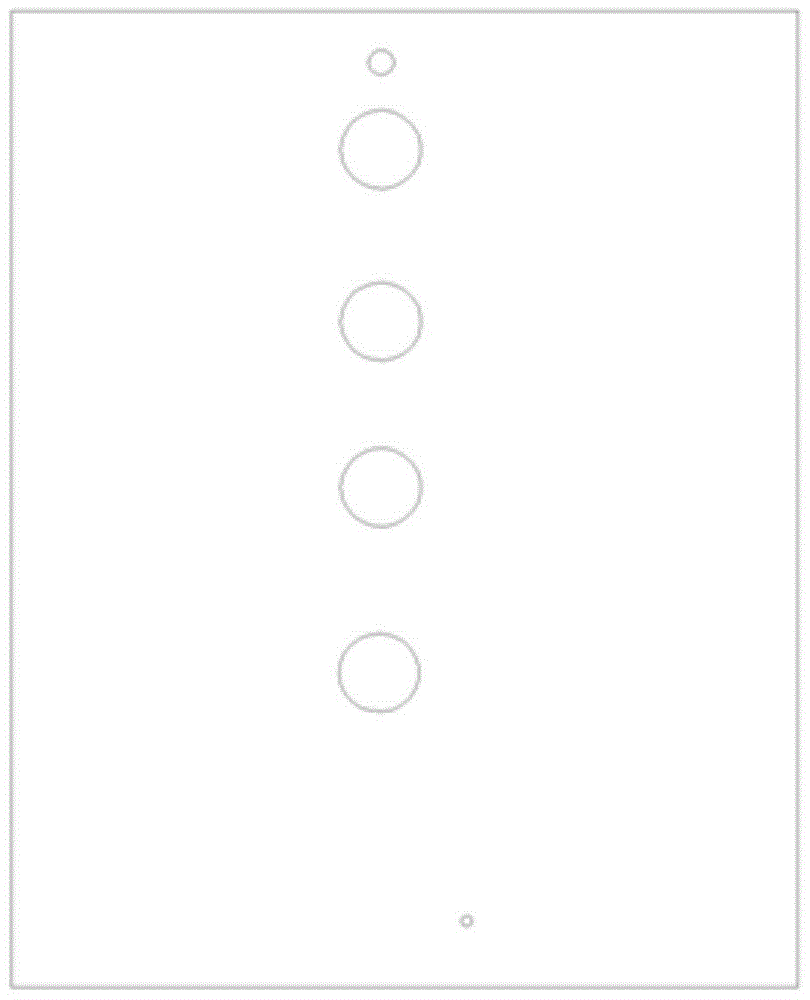
[0031] The microfluidic channel layer 300 includes a liquid channel 7 connecting the sample inlet and each sample reservoir, a liquid channel 8 connecting each sample reservoir with the corresponding reaction cell, the lower half of the sample reservoir, and the sample injection channel The sample buffer tank 5 and the reaction ...

Embodiment 2

[0038] Embodiment 2: Microfluidic chip workflow

[0039] Step 1: When adding samples, the microvalve 2 is opened, the microvalve 3 is closed, pressurized gas is introduced into the microvalve gas path 13 through the valve seat 12, and the liquid channel of the reservoir toward the reaction tank is closed, and the sample is injected from The hole 1 is injected, the sample flows through the liquid channel 7 into each sample reservoir 4, and the excess sample flows into the sample buffer pool 5;

[0040] Step 2: When all the sample reservoirs 4 are full, the microvalve 2 is closed, the microvalve 3 is opened, pressurized gas is introduced into the microvalve gas path 11 through the valve seat 10, and each reservoir 4 is closed and controlled The microvalve for liquid flow in the liquid channel 7 realizes the isolation between the sample reservoirs 4; open the microvalve that controls the liquid channel of each sample reservoir and the corresponding reaction cell, and press the elastic...

Embodiment 3

[0041] Embodiment 3: Manufacturing method of microfluidic chip

[0042] (1) Preparation of mold with microstructure on microfluidic chip

[0043] Computer-aided design software is used to design the microchannel and microstructure of the microfluidic chip, and the chromium plate is used to make the masks of the gas control channel layer and the microfluidic channel layer according to the design drawing.

[0044] Choose silicon wafers for photolithography and etching to make molds. First, clean the silicon wafers, dry the cleaned silicon wafers with nitrogen, and then put them on the homogenizer, take an appropriate amount of photoresist and apply it on the silicon wafer, and start the homogenizer Spin-coating photoresist, place the mask on the silicon wafer coated with photoresist and place it in a photolithography machine for exposure. After developing and post-baking, dry etching is used to obtain an upper gas control channel layer and a lower layer Mold for the microstructure of ...


PUM


Abstract

The invention discloses a micro-fluidic chip achieving multi-index detection, and relates to the field of micro-fluidic chip medical treatment detection. The micro-fluidic chip achieving multi-index detection comprises a gas control channel layer, an organic macromolecular polymer film layer and a micro-fluid channel layer. All the layers of materials are integrated, bonded and sealed to form the chip structure. The micro-fluidic chip is characterized in that the gas control channel layer comprises a sample inlet hole, a gas outlet hole, two pneumatic micro valves and upper portions of multiple liquid storage pools connected in series; holes are formed in the portions, corresponding to the sample inlet hole, the pneumatic micro valve structures, the liquid storage pools and the gas outlet hole, of the organic macromolecular polymer film; the micro-fluid channel layer is provided with lower portions of the liquid storage pools connected in series, multiple reaction pools, a liquid channel making all the liquid storage pools communicated and a liquid channel making the liquid storage pools and the reaction pools communicated. The micro-fluidic chip is simple in structure and convenient to use, the pneumatic micro valves are utilized for making the liquid storage pools and the reaction pools independent, mutual pollution of liquid among the reaction pools is avoided, the precision of a sample amount is improved, and reliability of detection results is guaranteed.

Description

Technical field [0001] The invention relates to the field of microfluidic chip analysis, in particular to a microfluidic chip for multi-index detection. Background technique [0002] A microfluidic chip is also called a laboratory on a chip, which refers to a biological or chemical laboratory built on a chip of a few square centimeters. It makes the basic operation units involved in the fields of biology and chemistry such as reaction, separation, culture, sorting, and detection into micro / nano-scale components, and integrates them on a small chip, forming a network of microchannels. Controllable fluid runs through the entire system to realize various functions of conventional biology or chemistry. Enzyme reactions, immune reactions, PCR reactions, enzyme-linked immunoassays and other reactions for the purpose of biochemical sample analysis can all be realized on the microfluidic chip. Because the microfluidic chip technology has the characteristics of small injection volume, h...

Claims


Application Information

Patent Timeline
Patent Type & Authority Applications(China)
IPC IPC(8): B01L3/00
Inventor 许行尚苏恩本罗雅赛任红霞金晶
Owner GETEIN BIOTECH
Why Eureka
Try Eureka