Surface patterning-modified substrate and preparation method therefor

A technology for substrates and substrate surfaces, applied in the field of surface patterned substrates and their preparation, can solve problems such as unstable hydrophilic and hydrophobic properties, cumbersome operation steps, etc., and achieve low cost, stable modification, and low processing costs Effect

Active Publication Date: 2015-12-23
黑玉星岩国际科学技术(北京)有限公司
View PDF4 Cites 17 Cited by
  • Summary
  • Abstract
  • Description
  • Claims
  • Application Information

AI Technical Summary

Problems solved by technology

However, most of these methods change the surface properties by chemically modifying the active groups on the surface of t

Method used


Image

  • Surface patterning-modified substrate and preparation method therefor
  • Surface patterning-modified substrate and preparation method therefor
  • Surface patterning-modified substrate and preparation method therefor

Examples


preparation example Construction

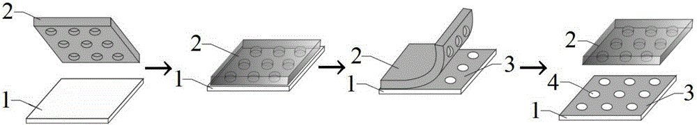
[0044] The invention provides a method for preparing a surface patterned substrate, the specific steps are as follows:

[0045] (1) Design a photolithographic mask according to the morphology of the desired hydrophilic region and hydrophobic region; Similarly, when using a positive mold photoresist, such as SU-8, the shape of the mask is the same as that of the required hydrophilic region; then, use negative mold lithography or positive mold lithography to prepare A PDMS (polydimethylsiloxane) stamp, the PDMS stamp includes a raised portion and a depressed portion, the shape of the raised portion corresponds to a hydrophobic region, and the shape of the depressed portion corresponds to a hydrophilic region;

[0046] (2) Treat the PDMS stamp and the substrate with plasma, so that the PDMS stamp and the substrate surface generate free radicals; wherein, the substrate is a substrate with a smooth surface and a hydrophilic group; the hydrophilic The water group is an alkoxy group, ...

Embodiment 1

[0060] The preparation of embodiment 1 glass substrate

[0061] Step 1: Make the positive mold by soft lithography technology

[0062] Throw the photoresist SU-8 (1070) on the cleaned and dried silicon wafer (700r18s, 2500r60s), and pre-baked to remove the solvent in the SU-8 glue (65°C 15min, 95°C 2hour), so that SU-8 The positive mold is better bonded to the silicon wafer, and then photolithography (3.5mJ / cm 2 ), the mask plate used in lithography is set according to the shape of the positive mold, and the photolithography time is 60s; then it is placed on a hot plate for post-baking (65°C 15min, 95°C 2hour), so that the positive mold and The silicon wafer is more closely bonded, and after being developed by a developer, the film is hardened (135°C) for more than 1 hour to achieve the effect of close adhesion between SU-8 and the silicon wafer, and the SU-8 anode with microstructure can be obtained. mold, and its height was measured to be about 20 μm.

[0063] Step 2: Pre...

Embodiment 2

[0069] Repeat Example 1 with the same steps described above, the difference is that in step 1, AZ-50 is used as the photoresist as AZ50, the mask plate is set according to the concave part of the PDMS stamp, and PDMS is prepared using the corresponding preparation process of AZ-50 seal.


PUM

PropertyMeasurementUnit
Thicknessaaaaaaaaaa
Diameteraaaaaaaaaa

Abstract

The invention discloses a surface patterning-modified substrate. The surface patterning-modified substrate comprises a substrate and a patterned nano thin layer, wherein the surface of the substrate is provided with hydrophilic groups, and the nano thin layer is a PDMS thin layer with thickness being smaller than 1 micron; the patterned nano thin layer and the substrate are bonded so as to form a hydrophilic region without the nano thin layer and a hydrophobic region with the nano thin layer, the hydrophilic region is used for adsorbing microfluid, the microfluid is water, a solution or a suspension, and the shape of a projection of the microfluid on the surface of the substrate is identical with the corresponding hydrophilic region. The invention also discloses a preparation method for the substrate and application of the substrate in the preparation of array chips. According to the surface patterning-modified substrate and the preparation method therefor, the surface of the substrate is subjected to patterning modification by using a simple and fast process, and the substrate has a broad application prospect in the preparation of microarray chips.

Description

technical field [0001] The invention belongs to the field of surface modification, and more specifically relates to a surface patterned modified substrate and a preparation method thereof. Background technique [0002] In recent years, microfluidic systems have had a significant impact in the fields of chemical engineering, bioengineering, and translational medicine. This microfluidic system combines materials science, chemical engineering, micro-electromechanical processing and other technologies to perform a series of operations such as sample injection, pretreatment, sample addition, sampling, reaction, and detection. Through the establishment of a large-scale integrated operating system, the analysis and screening throughput is higher, simpler and more effective. Because it is operated at the micron scale, it can also save sample costs and improve the accuracy of each unit experiment. The development of microfluidic systems will bring about a significant reduction in s...

Claims


Application Information

Patent Timeline
IPC IPC(8): B01L3/00B01J13/00
Inventor 刘笔锋李一伟陈璞王亚超冯晓均
Owner 黑玉星岩国际科学技术(北京)有限公司
Why Eureka
Try Eureka