Fiber-reinforced composite coiled sucker rod and production apparatus and method thereof

A composite material and fiber-reinforced technology, applied to chemical instruments and methods, drill pipes, drilling equipment, etc., can solve the problems of increasing axial tensile modulus, high cost, and inability to choose, so as to increase radial strength and Axial compressive strength, easy operation and transportation, and the effect of ensuring continuous stability

Active Publication Date: 2015-12-23
江苏众成复合材料有限责任公司
View PDF7 Cites 18 Cited by
  • Summary
  • Abstract
  • Description
  • Claims
  • Application Information

AI Technical Summary

Problems solved by technology

[0003] FRP sucker rods are prepared by pultrusion of glass fiber reinforced thermosetting resin at one time, and have been widely used. However, with the continuous improvement of the reliability requirements of modern oil production, FRP sucker rods can no longer meet the requirements. The main problems are as follows: 1) The partial wear resistance of the sucker rod is not good; 2) The axial tensile modulus is low and the deformation is large, which leads to a significant reduction in the effective stroke of the oil well pump, and the oil recovery efficiency is significantly reduced; 3) The fiberglass sucker rods are all fixed in length, with A metal joint is used to connect the roots with the metal couplings used in metal sucker rods. Due to the complex structure, it is difficult to process. At the same time, each fiberglass sucker rod uses two metal joints, which is expensive; Compared with the traditional metal sucker rod, the material of the FRP sucker rod has been changed except for the rod body, and the other parts of the whole sucker rod string have not changed. There are many column joints in the traditional metal sucker rod, and the probability of breakage is high, and the piston effect Obvious issues such as not resolved
However, in practical application, it was found that the sucker rod adopts a one-time integral processing method of pultrusion and coating (including wire feeding-resin-impregnated-coating-coating-preforming-curing-coiling process), and the coating layer is fiber Fabric-reinforced thermosetting resin not only increases the material cost, but also the partial wear resistance of the fiber fabric coating is not ideal; There are problems such as uneven lap width, extrusion of internal unidirectional fibers, and low transverse strength; in...

Method used


Image

  • Fiber-reinforced composite coiled sucker rod and production apparatus and method thereof
  • Fiber-reinforced composite coiled sucker rod and production apparatus and method thereof
  • Fiber-reinforced composite coiled sucker rod and production apparatus and method thereof

Examples


preparation example Construction

[0035] In addition, the present invention also improves a preparation method of the above-mentioned fiber-reinforced composite material continuous sucker rod, comprising the following steps:

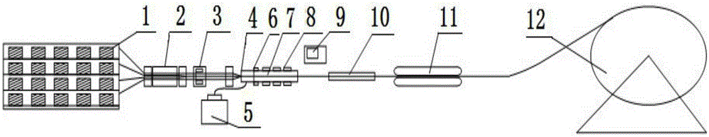
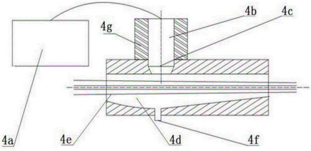
[0036] 1) Lead out multiple bundles of carbon fibers and H-grade glass fibers from the wire unwinding frame 1, and pass through the injection mold 4 under the traction of the traction device 11, and the injection mold 4 is prefilled with the epoxy resin matrix glue injected by the injection machine 5;

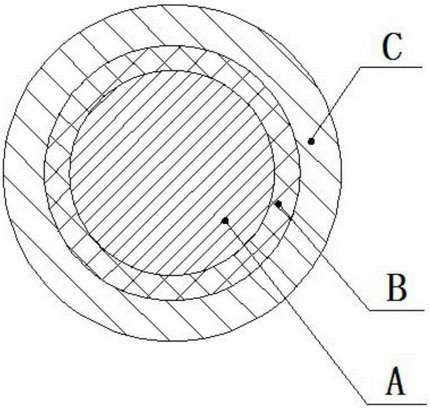
[0037] 2) Between the inner unidirectional carbon fiber A of the inner layer and the outer glass fiber layer C of the outer layer, use a winding machine or a weaving machine 3 to wind or weave an intermediate glass fiber layer B, and the thickness of the intermediate glass fiber layer B is 1 ~2mm, the winding or weaving is bidirectional winding or weaving, and the crossing angle of the two directions of winding or weaving is 15~85°; the winding or weaving middle glass fiber layer B enters ...

Embodiment 1

[0040] First, through the control operation of the control device 9, 170 T300-12K carbon fiber filaments and 130 H-grade glass fibers with a linear density of 24TEX are respectively entered into the pretreatment heating furnace 2 through the wire discharging holes of the wire unwinding frame 1. The furnace temperature is At 120°C, the traction speed is 0.15m / min, 170 T300-12K carbon fibers after heat treatment are bundled into a perfect circle with a diameter of 12mm, and pass through the core hole between the two winding machines;

[0041] The rotation directions of the two winding machines are opposite (facing the moving direction of the carbon fiber bundle, the first winding machine rotates clockwise, and the second winding machine rotates counterclockwise). Grade glass fiber, 8 H-grade glass fibers are drawn out in turn, and pass through the wire hole in the middle of the winding machine to form a 4mm wide glass fiber tape. The 4mm wide glass fiber tape is evenly wound on a...

Embodiment 2

[0046] According to implementation 1, change the number of unidirectional H-grade glass fibers in the outer layer to produce fiber-reinforced composite continuous sucker rods with different diameters: change the number of H-grade glass fibers with a linear density of 24TEX to 210, and 170 T300 -12K carbon fiber filaments enter the surface treatment furnace through the filament holes of the unwinding rack 1 respectively. The rest is the same to the heat treatment operation.

[0047] After heat treatment, 210 H-grade glass fibers with a linear density of 24TEX were bundled into 15 bundles of 14 fibers, which were evenly distributed on the outside of the circular carbon fiber bundles wrapped with two layers of glass fibers, and bundled together into a diameter of 22.2 The perfect circle of mm enters the injection mold 4, and the injection mold 4 is filled with the epoxy resin glue injected by the injection machine 5;

[0048] The fully impregnated fiber bundle enters a perfect c...


PUM

PropertyMeasurementUnit
Thicknessaaaaaaaaaa
Diameteraaaaaaaaaa
Linear densityaaaaaaaaaa

Abstract

The invention discloses a fiber-reinforced composite coiled sucker rod and belongs to the technical field of oil production equipment in the petroleum industry. The fiber-reinforced composite coiled sucker rod has three structural layers stacked in order, namely an inner carbon fiber layer (A), an intermediate glass fiber layer (B) and an outer glass fiber layer (C) orderly from inside to outside. The inner carbon fiber layer is made of unidirectional carbon fibers arranged axially along a rod body. The intermediate glass fiber layer is made of H-grade glass fibers arranged transversely along the rod body and is bidirectionally wound or knitted to the inner carbon fiber layer. The outer glass fiber layer is made of unidirectional H-grade glass fibers arranged axially along the rod body. The sucker rod is made of resin matrix which is an epoxy resin system; the carbon fibers and the H-grade glass fibers are used as reinforcing materials. The invention further provides a production apparatus and method of the sucker rod. The sucker rod is good in corrosion resistance, has few connectors, is low in cost and low breaking rate, has slight piston effect and moderate modulus and is convenient to curl, transport, operate and use.

Description

technical field [0001] The invention relates to a sucker rod for industrial oil extraction, in particular to a fiber-reinforced composite material continuous sucker rod and a preparation device and method thereof, belonging to the technical field of oil production equipment in the petroleum industry. Background technique [0002] In the production of petroleum industry, the corrosion problem is an urgent problem to be solved in the oil field production process. The sucker rod is the key component connecting the oil pumping unit and the oil sucking pump. It is subjected to complex forces and has a harsh working environment. It is easy to be corroded and seriously affect its service life, causing great cost waste to oilfield production. Due to the characteristics of light weight, high strength and corrosion resistance, composite sucker rods have begun to gradually replace traditional metal sucker rods. The currently used composite sucker rods mainly include glass fiber reinfor...

Claims


Application Information

Patent Timeline
IPC IPC(8): E21B17/00B32B17/02B32B17/12B32B9/00B29C70/52B29C70/38
Inventor 崔昌瑞赵得智
Owner 江苏众成复合材料有限责任公司
Why Eureka
Try Eureka