Eureka AIR delivers breakthrough ideas for toughest innovation challenges, trusted by R&D personnel around the world.

Nickel-lanthanum composite material cathode and direct carbon fuel cell and preparation method thereof

A composite material and fuel cell technology, which is applied in fuel cells, molten electrolyte fuel cells, battery electrodes, etc., can solve the problems of negative ion conductivity, low current density and power density, and high production cost that affect the catalytic activity of cathode oxygen dissociation reduction , to achieve the effect of low cost, high power density and current density, and easy control of composition

Active Publication Date: 2015-12-30
SHANXI YUXIANG INFORMATION TECH CO LTD +2
View PDF7 Cites 8 Cited by
  • Summary
  • Abstract
  • Description
  • Claims
  • Application Information

AI Technical Summary

Problems solved by technology

[0011] At present, the latest foreign DCFC can obtain high power density at high operating temperature (800°C-1000°C), but the current density and power density obtained when operating at medium temperature (500°C-650°C) are relatively low. Therefore, improving the power density and current density under medium temperature working conditions is called an urgent problem in the development of DCFC.
The rare earth oxide composite cathode material mentioned in the invention of the Chinese Academy of Sciences has initially possessed some characteristics and properties of the cathode material, but first of all, the composition of the material is relatively complex and the production cost is high; secondly, the combination of complex oxides will affect the cathode oxygen dissociation Catalytic activity and cathodic ionic conductivity for reduction

Method used


Image

  • Nickel-lanthanum composite material cathode and direct carbon fuel cell and preparation method thereof
  • Nickel-lanthanum composite material cathode and direct carbon fuel cell and preparation method thereof
  • Nickel-lanthanum composite material cathode and direct carbon fuel cell and preparation method thereof

Examples


Embodiment Construction

[0039] The present invention will be further elaborated below through specific embodiments in conjunction with the accompanying drawings.

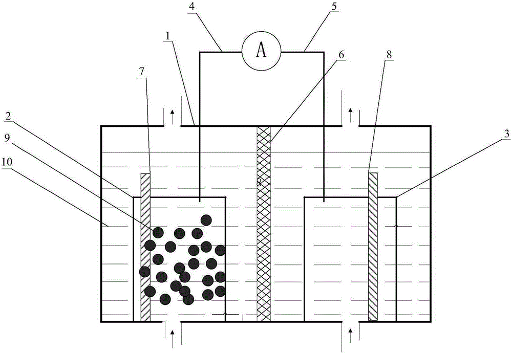
[0040] Such as figure 1 As shown, the direct carbon fuel cell of this embodiment includes: a reaction device 1, an anode compartment 2, a cathode compartment 3, an anode 7, a cathode 8, an anode current collector 4, a cathode current collector 5, and a microporous separator 6 , molten alkali electrolyte 10 and carbon fuel 9; wherein, in reaction device 1, be full of molten alkali electrolyte 10; Cylindrical anode plate bin 2 and cathode plate bin 3 are respectively arranged at the bottom of reaction device 1; Anode 7 and cathode 8 are respectively Placed in the anode plate bin 2 and the cathode plate bin 3; the anode current collector plate 4 and the cathode current collector plate 5 with holes penetrate and extend into the anode plate bin and the cathode plate bin from the top of the reaction device respectively; A microporous separator ...


PUM

PropertyMeasurementUnit
current densityaaaaaaaaaa

Abstract

The invention discloses a nickel-lanthanum composite material cathode and a direct carbon fuel cell and a preparation method thereof. The nickel-lanthanum composite material cathode includes two materials, wherein the first material is nickel, and the second material is lanthanide metal or lanthanum oxide La2O3. The nickel-lanthanum composite material cathode facilitates manufacture of an amorphous-state nanocrystalline thin-film material which is large in area and complicated in shape and is suitable for continuous operation and large-scale production. In addition, the composition of an alloy film is easy to control, a production process is simple, the cost is lower and the like. The direct carbon fuel cell (DCFC) adopting the nickel-lanthanum composite material cathode has stable discharge performance at intermediate temperature, outputs higher power density and current density and has higher fuel conversion efficiency. A nickel-lanthanum composite material adopted by the nickel-lanthanum composite material cathode is indissoluble and does not pollute a molten alkali electrolyte and a molten carbonate electrolyte.

Description

technical field [0001] The invention relates to the field of direct carbon fuel cell preparation, in particular to a nickel-lanthanum composite cathode, a direct carbon fuel cell and a preparation method thereof. Background technique [0002] Direct Carbon Fuel Cell (Direct Carbon Fuel Cell, DCFC) is a kind of fuel cell that uses carbon and its derivatives as fuel. It has outstanding advantages such as high energy conversion efficiency, environmental friendliness, and wide fuel adaptability. The total electrode reaction of DCFC is C+O 2 =CO 2 , under the standard state, the entropy change (DS) of this reaction is close to 0, and the Gibbs free energy change is almost equal to the enthalpy change. Therefore, the theoretical efficiency of DCFC can reach 100%, while the theoretical efficiencies of fuel cells fueled by hydrogen and methane are 83% and 91%, respectively. In addition, the theoretical efficiency of DCFC does not decrease with the increase of temperature. The the...

Claims


Application Information

Patent Timeline
Patent Type & Authority Applications(China)
IPC IPC(8): H01M4/86H01M4/88H01M8/14H01M8/22
CPCH01M4/8652H01M4/8875H01M8/143H01M8/22Y02E60/50Y02P70/50
Inventor 许云翔王亚斌王世虎
Owner SHANXI YUXIANG INFORMATION TECH CO LTD
Why Eureka
Eureka Blog
Learn More