Method for extracting methane from mixed gas containing methane, hydrogen and nitrogen

A mixed gas and methane technology, which is applied in the fields of hydrocarbons, chemical instruments and methods, organic chemistry, etc., can solve the problems of high investment cost, poor separation effect, and low product gas recovery rate, so as to improve the reflux ratio and reduce the load , the effect of reducing energy consumption

Active Publication Date: 2016-01-20
SUZHOU XINGLU AIR SEPARATION PLANT SCI & TECH DEV CO LTD
View PDF9 Cites 3 Cited by
  • Summary
  • Abstract
  • Description
  • Claims
  • Application Information

AI Technical Summary

Problems solved by technology

Although the membrane separation technology is simple to operate and low in energy consumption, the investment cost is relatively high and the separation effect is poor. Although the pressure swing adsorption method is convenient and fast, the recovery rate of the product gas is low due to the similar adsorption properties of methane and nitrogen. and difficult to separate CH 4 and N 2 , while low-temperature rectification technology can directly separate high-purity methane and nitrogen

Method used


Image

  • Method for extracting methane from mixed gas containing methane, hydrogen and nitrogen
  • Method for extracting methane from mixed gas containing methane, hydrogen and nitrogen

Examples


Embodiment 1

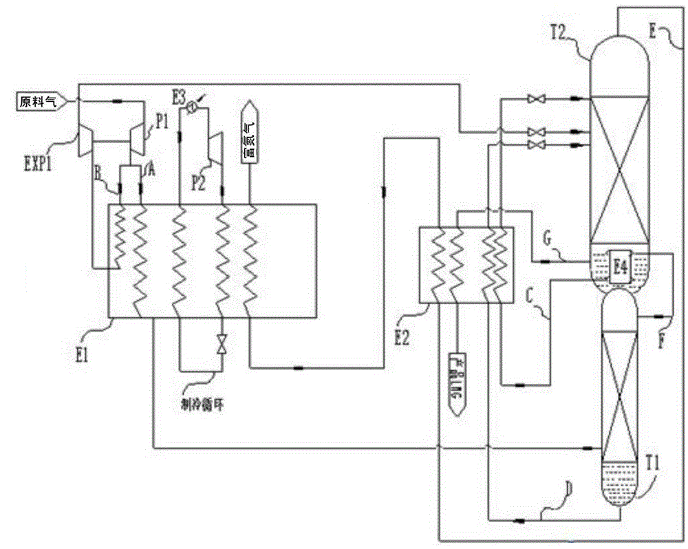
[0031] Such as figure 1 shown in figure 1 In , the equipment represented by each mark is as follows: P1-boosting end of raw gas expander; P2-mixed refrigerant cycle compressor; E1-main heat exchanger; E2-subcooler; E3-mixed refrigerant cooler; E4-condensing evaporator; EXP1-expansion end of raw material expander; T1-high pressure tower; T2-low pressure tower; FL-gas-liquid separator.

[0032] The air streams represented by each mark are as follows: air stream A-the feed gas entering the high-pressure tower after precooling; air stream B-the feed gas entering the low-pressure tower after compression and expansion; air stream C-subcooling and entering the high-pressure tower top nitrogen condensate of the low-pressure tower; air stream D -Crude methane at the bottom of the high-pressure column entering the low-pressure column; gas stream E-nitrogen at the top of the low-pressure column for reheating; gas stream F-gas stream from the top of the high-pressure column; gas stream G...

Embodiment 2

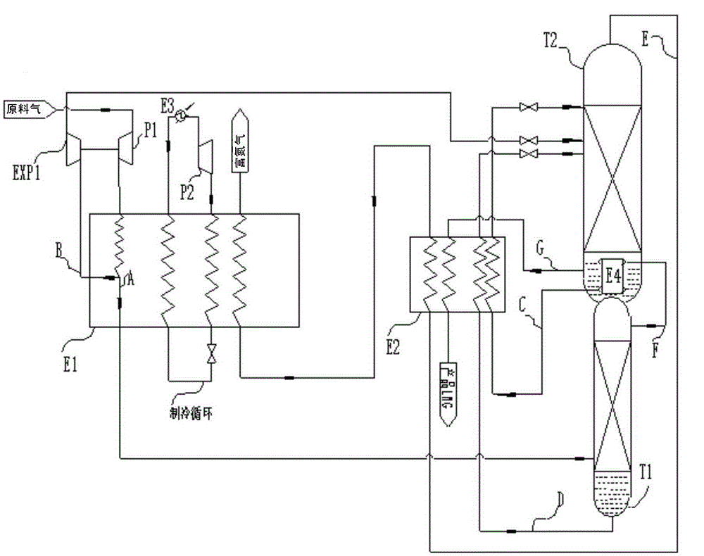
[0042] Such as figure 2 shown in figure 2 In , the equipment represented by each mark is as follows: P1-boosting end of raw gas expander; P2-mixed refrigerant cycle compressor; E1-main heat exchanger; E2-subcooler; E3-mixed refrigerant cooler; E4-condensing evaporator; EXP1-expansion end of raw material expander; T1-high pressure tower; T2-low pressure tower; FL-gas-liquid separator.

[0043] The air streams represented by each mark are as follows: air stream A-the feed gas entering the high-pressure tower after precooling; air stream B-expanding the feed gas entering the low-pressure tower; air stream C-subcooling and entering the high-pressure tower top nitrogen condensate of the low-pressure tower; The crude methane at the bottom of the high-pressure tower that enters the low-pressure tower; the gas stream E-nitrogen at the top of the low-pressure tower for reheating; the gas stream F-the gaseous stream drawn from the top of the high-pressure tower; the gas stream G-the ...


PUM


Abstract

The invention discloses a method for extracting methane from mixed gas containing the methane, hydrogen and nitrogen. The method comprises the steps that feed gas is divided into two steams, namely, an air stream A and an air stream B, and the air stream A enters a high-pressure tower to be rectified and separated after being cooled through a main heat exchanger; the air stream B is pumped out from the heat exchanger after being cooled for a certain stage through the main heat exchanger, the pumped-out air stream B is directly fed into a low-pressure tower to be rectified after being depressurized, refrigerated and cooled through an expansion machine, and a liquid methane product is obtained at the tower bottom. Or after the feed gas enters the main heat exchanger and is cooled to a certain stage, the feed gas is divided into the two streams, namely, the air stream A and the air stream B, wherein the air stream A continuously enters the main heat exchanger and is cooled, then the cooled air stream A enters the high-pressure tower to be rectified and separated, the air stream B is directly fed into the low-pressure tower to be rectified after being depressurized, refrigerated and cooled through the expansion machine, and the liquid methane product is obtained at the tower bottom. By means of the method for extracting the methane from the mixed gas containing the methane, the hydrogen and the nitrogen, non-pressurized liquified natural gas with the purity being 98 percent or above can be directly obtained, the product does not need to be liquified again, energy consumption can be greatly reduced, the recovery rate of the methane can reach up to 99.5 percent, the recovery rate of the nitrogen can reach up to 99 percent, and the rewarmed nitrogen can be used as industrial nitrogen.

Description

technical field [0001] The invention relates to a method for extracting methane from a mixed gas containing methane, hydrogen and nitrogen. Background technique [0002] Coal bed methane, synthetic ammonia release gas, and coal upgrading pyrolysis tail gas are all mixed gases containing methane, hydrogen, nitrogen and other elements, and their main components include: CO 2 、H 2 、CH 4 , CO, H 2 O, N 2 and other hydrocarbons and sulfides. [0003] In the current mixture (mainly CH 4 、H 2 and N 2 ) Methane separation technology includes membrane separation method and pressure swing adsorption method. Although the membrane separation technology is simple to operate and low in energy consumption, the investment cost is relatively high and the separation effect is poor. Although the pressure swing adsorption method is convenient and fast, the recovery rate of the product gas is low due to the similar adsorption properties of methane and nitrogen. and difficult to separate...

Claims


Application Information

Patent Timeline
IPC IPC(8): C07C9/04C07C7/00C07C7/04
CPCF25J3/0209F25J3/0233F25J3/0257F25J2200/06F25J2210/06F25J2215/04F25J2230/30F25J2240/02F25J2270/12F25J2270/66
Inventor 薛鲁雷青青颜爱国
Owner SUZHOU XINGLU AIR SEPARATION PLANT SCI & TECH DEV CO LTD
Why Eureka
Try Eureka