
Surface coating method of cathode material for lithium-ion battery

A technology for lithium-ion batteries and positive electrode materials, applied in battery electrodes, secondary batteries, circuits, etc., can solve problems such as increasing the contact between electrolyte and electrode materials, increasing processing procedures and production costs, and being unable to control uniform carbon coating. , achieve good commercial application prospects, improve electrochemical performance, and improve the effect of reducing tap density

Active Publication Date: 2016-02-10
HEFEI GUOXUAN HIGH TECH POWER ENERGY
View PDF3 Cites 10 Cited by
  • Summary
  • Abstract
  • Description
  • Claims
  • Application Information

AI Technical Summary

Problems solved by technology

The coating of oxides (such as MgO, S.J.Shi, J.P.Tu, Y.Y.Tang, et al., ElectrochimicaActa, 2013, 88, 671-679.) can reduce the contact between the electrode and the electrolyte, thereby effectively reducing the corrosion of the electrode by the electrolyte, but at the same time It will also reduce the electrical conductivity of the electrode material, while carbon coating can improve the electrical conductivity and rate performance of the material, but it will significantly reduce the tap density of the material, increasing subsequent processing procedures and production costs
At the same time, the commonly used carbon coating method cannot control the uniform carbon coating and will lead to the reduction of the positive electrode material.
As we all know, reducing the size of the material can also effectively improve the electrochemical performance of the material, but reducing the size of the material will increase the contact between the electrolyte and the electrode material, reducing the cycle performance of the material

Method used


Image

  • Surface coating method of cathode material for lithium-ion battery
  • Surface coating method of cathode material for lithium-ion battery

Examples


Embodiment 1

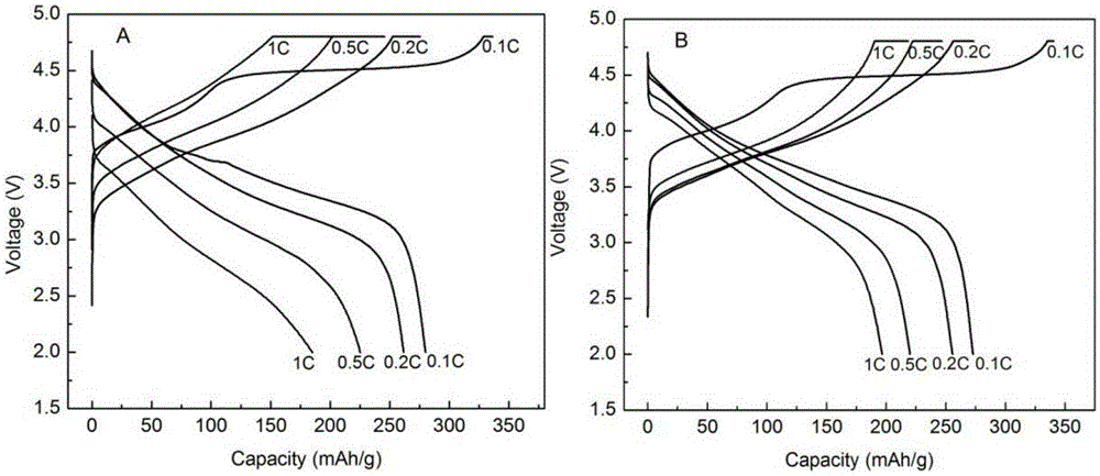
[0025] Example 1: Preparation of Li-MgO and carbon-coated Li 1.2 mn 0.56 Ni 0.16 co 0.08 o 2

[0026] The ground Li 1.2 mn 0.56 Ni 0.16 co 0.08 o 2 Add in a solution containing magnesium acetate and LiOH, wherein magnesium accounts for 2% of the total mass of the positive electrode material, and Li accounts for 0.2% of the total mass of the positive electrode material. The mixed solution is ultrasonicated for 2h, then stirred at 60°C until dry, and finally at 80°C ℃ in an oven for 12 hours; the dried samples were heated in a tube furnace at 1 ℃ / min to 130 ℃ and maintained for 1 hour, and then heated to 600 ℃ at 2 ℃ / min and maintained for 2 hours. During the whole process, the tube furnace O 2 . When the sample coated with Li-MgO dropped to room temperature, the gas was switched to CH 4 , O 2 and CO 2 The mixed gas, where CH 4 , O 2 and CO 2 The volume ratio is 5:1:4, then the temperature is raised to 500°C for 1 hour, and finally it is lowered to room temperat...

Embodiment 2

[0029] Example 2: Preparation of Li-MgO and carbon-coated LiMn 0.2 Ni 0.6 co 0.2 o 2

[0030] The ground LiMn 0.2 Ni 0.6 co 0.2 o 2 Add in a solution containing magnesium acetate and LiOH, wherein magnesium accounts for 2% of the total mass of the positive electrode material, and Li accounts for 0.2% of the total mass of the positive electrode material. The mixed solution is ultrasonicated for 2h, then stirred at 60°C until dry, and finally at 80°C ℃ in an oven for 12 hours; the dried samples were heated in a tube furnace at 1 ℃ / min to 130 ℃ and maintained for 1 hour, and then heated to 600 ℃ at 2 ℃ / min and maintained for 2 hours. During the whole process, the tube furnace O 2 . When the sample coated with Li-MgO dropped to room temperature, the gas was switched to CH 4 , O 2 and CO 2 The mixed gas, where CH 4 , O 2 and CO 2 The volume ratio is 5:1:4, then the temperature is raised to 500°C for 1 hour, and finally cooled to room temperature.

Embodiment 3

[0031] Example 3: Preparation of Li-MgO and carbon-coated Li 1.2 mn 0.56 Ni 0.16 co 0.08 o 2

[0032] The ground Li 1.2 mn 0.56 Ni 0.16 co 0.08 o 2Add in a solution containing magnesium acetate and LiOH, wherein magnesium accounts for 5% of the total mass of the positive electrode material, and Li accounts for 0.5% of the total mass of the positive electrode material. The mixed solution is ultrasonicated for 2h, then stirred at 60°C until dry, and finally at 80°C ℃ in an oven for 12 hours; the dried samples were heated in a tube furnace at 1 ℃ / min to 130 ℃ and maintained for 1 hour, and then heated to 600 ℃ at 2 ℃ / min and maintained for 2 hours. During the whole process, the tube furnace O 2 . When the sample coated with Li-MgO dropped to room temperature, the gas was switched to CH 4 , O 2 and CO 2 The mixed gas, where CH 4 , O 2 and CO 2 The volume ratio is 5:1:4, then the temperature is raised to 500°C for 1 hour, and finally it is lowered to room temperatu...


PUM


Abstract

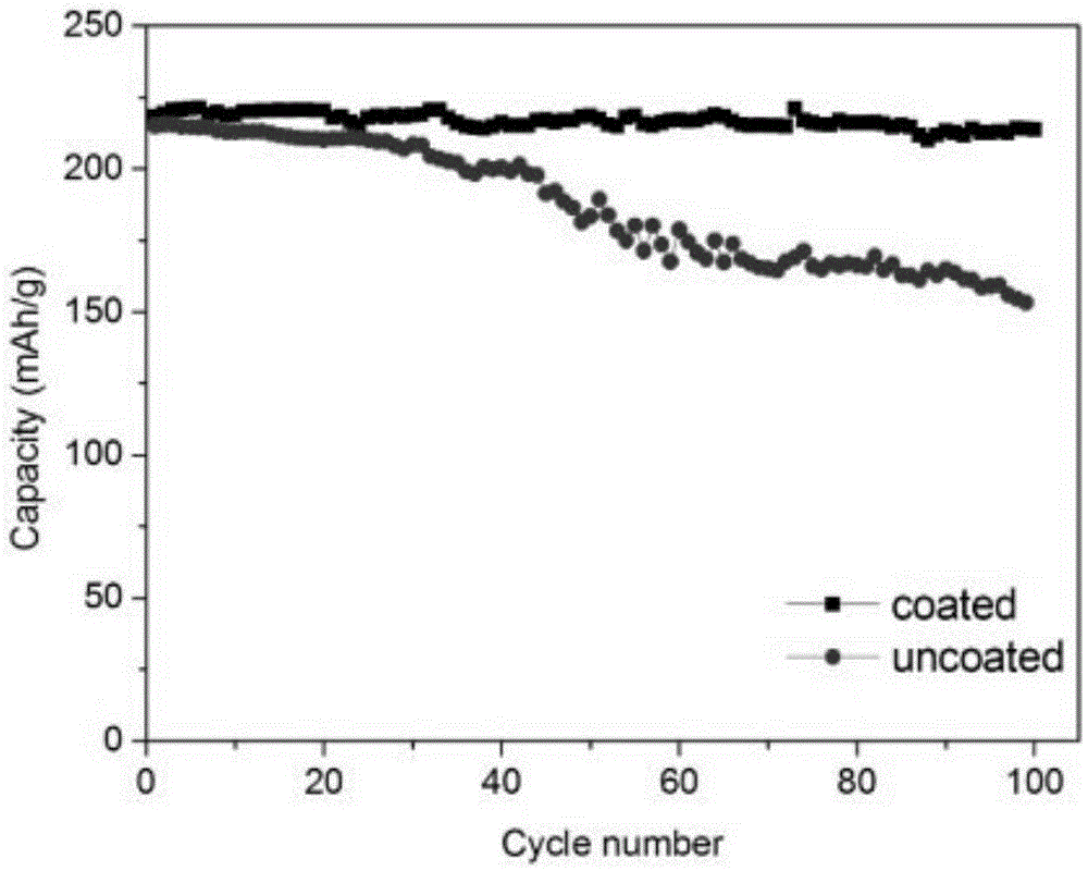
The invention discloses a surface coating method of a cathode material for a lithium-ion battery. The method comprises the following steps: adding the cathode material for the lithium-ion battery to a magnesium salt solution, simultaneously adding a certain amount of lithium compound, carrying out ultrasound for 30-180 minutes, stirring the solution at 50-80 DEG C until dry, and putting the sample into a drying oven at 80 DEG C for drying; slowly heating the dried sample to 110-130 DEG C in a tube furnace, maintaining the temperature for 1-2 hours, heating the sample to 500-600 DEG C at the speed of 2 DEG C / min, maintaining the temperature for 2 hours, and introducing an oxidizing atmosphere to the tube furnace in the overall process; and burning the sample in the tube furnace. According to the cathode material for the lithium-ion battery, oxide coating is combined with carbon coating; and the amount of the oxide can be reduced, so that reduction of the conductivity caused by the oxide coating is well improved; meanwhile, reduction of the tap density caused by traditional carbon coating can also be improved; and the rate capability and the cycle performance of the material are improved. The carbon coating is carried out on the cathode material for the lithium-ion battery by a catalysis method; the coated carbon is uniform and controlled in thickness; and meanwhile, reduction of the cathode material caused by coated carbon can be reduced.

Description

technical field [0001] The invention relates to the field of lithium ion batteries, in particular to a method for coating the surface of positive electrode materials of lithium ion batteries. Background technique [0002] Among the current secondary batteries, lithium-ion batteries have unique advantages such as high working voltage, high energy density, long cycle life, low self-discharge, no memory effect, no pollution, and good safety performance, so they have been widely used and promoted. The development of new electrode materials with high performance and low cost has always been the research direction of lithium-ion batteries. According to the requirements of the national "Twelfth Five-Year Plan" for new energy vehicles, the energy density of power batteries should reach 150Wh / kg in 2015 and 300Wh / kg by 2020. [0003] Lithium-rich manganese-based cathode materials have a high energy density and a discharge specific capacity twice that of the current cathode materials...

Claims


Application Information

Patent Timeline
IPC IPC(8): H01M4/62H01M4/36H01M4/505H01M4/525H01M10/0525
CPCH01M4/366H01M4/505H01M4/525H01M4/62H01M4/625H01M10/0525Y02E60/10
Inventor 高玉仙丁楚雄
Owner HEFEI GUOXUAN HIGH TECH POWER ENERGY
Learn More