Device for flue gas desulfurization and denitrification

A flue gas and denitrification technology, which is applied in the direction of gas treatment, use of liquid separation agent, membrane technology, etc., can solve the problems of long processing time of flue gas desulfurization and denitrification equipment, reduced service life of water pumps, and large water pumping capacity of water pumps, etc.

Active Publication Date: 2016-03-30
史汉祥
View PDF7 Cites 9 Cited by
  • Summary
  • Abstract
  • Description
  • Claims
  • Application Information

AI Technical Summary

Problems solved by technology

[0003] The applicant has applied for flue gas desulfurization and denitrification equipment, such as Chinese patent CN201310562110.2, and found other problems in the process of use. Specifically, in order to increase the redox efficiency of waste residue in the slurry tank, it will The air is flushed into the material tank, and a large number of air bubbles are generated when the air is injected into the slurry tank. The pumping capacity of the water pump is very large, and the service life of the pump is easily reduced if there are too many bubbles.
In addition, the treatment time of flue gas desulfurization and denitrification equipment with return pipe structure is long

Method used


Image

  • Device for flue gas desulfurization and denitrification

Examples


Embodiment Construction

[0014] Combine below figure 1 A detailed description will be made to the specific embodiment of the present invention.

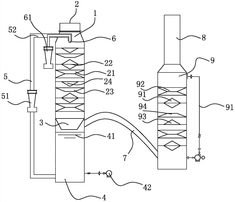
[0015] Such as figure 1 The shown equipment for flue gas desulfurization and denitrification includes a first-stage multiphase reactor 1, a water circulation system 5, an isolation cover 3, a slurry tank 4, a slurry discharge device 42, an outlet pipe 7, and a second-stage multi-phase reactor. Phase reactor 9 and water shower 91.

[0016] The top of the first-stage multiphase reactor is the flue gas inlet 2. The first multiphase reactor 1 includes a conical member composed of the first cone and the first conical ring below it. The cone of the first cone The bottom faces the first conical ring. Both the first conical ring and the first vertebral body have two structures, one is that the diameter of the conical surface of the first conical ring 23 is reduced from top to bottom, and the maximum diameter of the first vertebral body 24 is not less than that of...


PUM


Abstract

The invention relates to the field of air purification devices and discloses a device for flue gas desulfurization and denitrification. The device comprises a primary multi-phase reactor, a water circulation system, an isolation hood, a slurry pool, a slurry discharge device, a gas outlet pipe, a second multi-phase reactor and a water spraying device, wherein the water circulation system comprises a water pump and a water pipe; the water inlet end of the water pipe of the water pump is communicated with the circulation slurry pool; the water outlet end of the water pipe is positioned in the center of the primary multi-phase reactor and positioned above a first conical ring; the water pipe is internally provided with a gas inlet pipe and sleeves the outer side of the gas inlet pipe; the outer end of the gas inlet pipe is connected with the gas pump; the gas outlet end of the gas inlet pipe is positioned below the water outlet end of the water pipe; the gas outlet pipe is n-shaped; the water spraying device sprays water into the secondary multi-phase reactor, the temperature in the secondary multi-phase reactor does not exceed 35 DEG C. The device for flue gas desulfurization and denitrification has the advantages that the desulfurization and denitrification effect and dust removal effect on flue gas generated by burning are good, the desulfurization rate and the denitrification rate for flue gas are high, the dust purification rate for fine particles PM2.5 is high, and especially the CO2 emission amount can be effectively controlled.

Description

technical field [0001] The invention relates to the field of air purification equipment, in particular to equipment for purifying flue gas produced by industrial combustion and desulfurizing and denitrifying the flue gas. Background technique [0002] The industrial flue gas produced by industrial fuel combustion mainly refers to a large amount of flue gas and dust produced by the combustion of industrial boilers. In my country, SO 2 About 90% of emissions are mainly from coal combustion, and 90% of NOx comes from fuel combustion. Thermal power enterprises and metal smelting enterprises will produce a large amount of flue gas in the production process. Therefore, desulfurization and denitrification are the most important methods for China to control coal-burning pollution and improve the atmospheric environment. Target. For example, in metal smelting steel plants, the exhaust gas contains sulfur oxides, nitrogen oxides, carbide steel slag and other waste slag dust; the exha...

Claims


Application Information

Patent Timeline
Patent Type & Authority Applications(China)
IPC IPC(8): B01D53/80B01D53/60B01D53/62B01D53/96B01D47/06
CPCB01D47/06B01D53/60B01D53/62B01D53/80B01D53/96B01D2251/102B01D2258/0283Y02P70/10
Inventor 史汉祥
Owner 史汉祥
Why Eureka
Try Eureka