
Iridium complex phosphorescent material-based and doped organic ultraviolet detector

A technology of iridium complexes and phosphorescent materials, applied in the field of organic ultraviolet detection devices, can solve problems such as low photoresponsivity, and achieve the effects of high responsivity, improved production efficiency, and strong ultraviolet light absorption

Inactive Publication Date: 2016-04-13
UNIV OF ELECTRONIC SCI & TECH OF CHINA
View PDF2 Cites 2 Cited by
  • Summary
  • Abstract
  • Description
  • Claims
  • Application Information

AI Technical Summary

Problems solved by technology

[0005] In order to solve the problem of low photoresponsivity of existing organic ultraviolet detection devices, the present invention provides an organic ultraviolet detection device based on iridium complex phosphorescent material doping, by adding iridium with strong ultraviolet absorption into the ultraviolet active layer Complex Phosphorescent Materials for Improving the Photoresponsivity of Organic Ultraviolet Detection Devices

Method used


Image

  • Iridium complex phosphorescent material-based and doped organic ultraviolet detector
  • Iridium complex phosphorescent material-based and doped organic ultraviolet detector
  • Iridium complex phosphorescent material-based and doped organic ultraviolet detector

Examples


Embodiment 1

[0046] Embodiment one (control group)

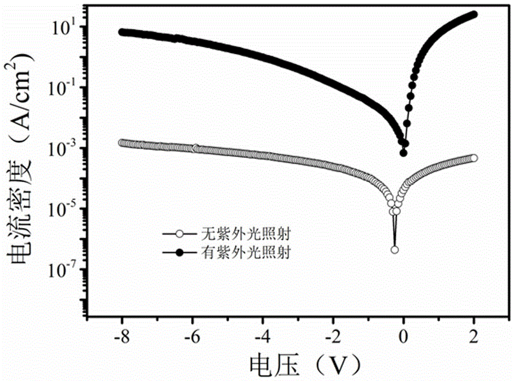
[0047] Clean the substrate composed of the substrate and the transparent conductive anode ITO, and dry it with nitrogen after cleaning; spin-coat PEDOT:PSS (1500rpm, 15nm) on the surface of the transparent conductive anode ITO to prepare the anode buffer layer, and the formed The film is baked (150°C, 30min); the electron blocking layer TAPC5nm is evaporated on the anode buffer layer, and the electron blocking layer is prepared by spin coating PVK:ZnO (60%:40%) ultraviolet photoactive layer (1500rpm, 120nm ), and baked (100° C., 15 min); the hole blocking layer Bphen5nm was prepared by evaporation on the surface of the ultraviolet photoactive layer, and the metal anode Ag (100nm) was evaporated on the hole blocking layer. Under standard test conditions: 350nm, 0.6mW / cm 2 Under the condition of -2V for ultraviolet light, the measured responsivity of the device is 1.5A / W.

Embodiment 2

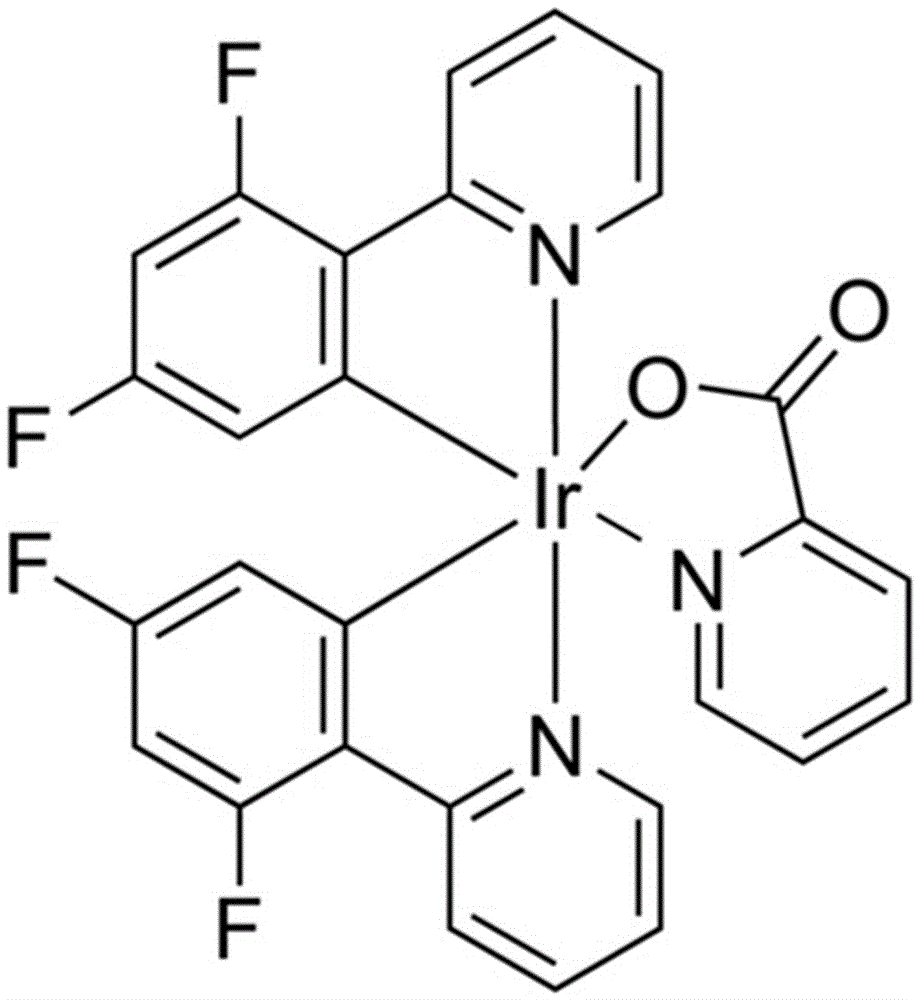
[0049] Clean the substrate composed of the substrate and the transparent conductive anode ITO, and dry it with nitrogen after cleaning; spin-coat PEDOT:PSS (1500rpm, 15nm) on the surface of the transparent conductive anode ITO to prepare the anode buffer layer, and the formed The film was baked (150°C, 30min); the electron blocking layer TAPC5nm was evaporated on the anode buffer layer, and PVK:FIrpic:ZnO (60%:1%:39%) was prepared by spin coating on the electron blocking layer for ultraviolet light activity layer (1500rpm, 120nm), and baked (100°C, 15min); the hole blocking layer Bphen5nm was prepared by evaporation on the surface of the ultraviolet photoactive layer, and the metal anode Ag (100nm) was evaporated on the hole blocking layer. Under standard test conditions: 350nm, 0.6mW / cm 2 Under the condition of -2V for ultraviolet light, the measured responsivity of the device is 3.2A / W.

Embodiment 3

[0051] Clean the substrate composed of the substrate and the transparent conductive anode ITO, and dry it with nitrogen after cleaning; spin-coat PEDOT:PSS (1500rpm, 15nm) on the surface of the transparent conductive anode ITO to prepare the anode buffer layer, and the formed The film is baked (150°C, 30min); the electron blocking layer TAPC5nm is evaporated on the anode buffer layer, and the electron blocking layer is prepared by spin coating PVK:FIrpic:ZnO (60%:5%:35%) UV photoactive layer (1500rpm, 120nm), and baked (100°C, 15min); the hole blocking layer Bphen5nm was prepared by evaporation on the surface of the ultraviolet photoactive layer, and the metal anode Ag (100nm) was evaporated on the hole blocking layer. Under standard test conditions: 350nm, 0.6mW / cm 2 Under the condition of -2V for ultraviolet light, the measured responsivity of the device is 4.5A / W.


PUM

PropertyMeasurementUnit
Thicknessaaaaaaaaaa
Thicknessaaaaaaaaaa

Abstract

The invention belongs to the technical field of organic photoelectrons, discloses an iridium complex phosphorescent material-based and doped organic ultraviolet detector, and aims at solving the problem of low photo responsivity of the organic ultraviolet detector. The iridium complex phosphorescent material-based and doped organic ultraviolet detector comprises a transparent substrate, a conductive anode, an anode buffer layer, an electron blocking layer, an ultraviolet active layer, a hole blocking layer and a metal anode from bottom to top. The organic ultraviolet detector is characterized in that the ultraviolet active layer comprises the following components in percentage by weight: 56%-60% of an electron donor, 34%-39% of an electron acceptor and 1%-10% of an iridium complex phosphorescent material. The iridium complex phosphorescent material disclosed by the invention has relatively high ultraviolet absorptivity, relatively long phosphorescence lifetime and good thermo-chemical stability, and is effectively combined with a donor-acceptor hybrid material; and through the phosphorescence effect of an iridium complex, the absorbed short-wave ultraviolet light is transmitted to the electron acceptor through triplet energy, so that the production efficiency of excitons is improved; and the photo responsivity of the detector is improved.

Description

technical field [0001] The invention belongs to the technical field of organic optoelectronics, and discloses an organic ultraviolet detection device based on iridium complex phosphorescent material doping. Background technique [0002] Ultraviolet light has a huge impact on human activities, so people started research on devices that can accurately measure ultraviolet radiation - ultraviolet detectors. Ultraviolet detectors have many applications in practice. They can be used to detect the intensity of ultraviolet rays in the atmosphere to prevent ultraviolet rays from harming the human body. Ultraviolet detectors can also be used to detect ultraviolet exposure, ultraviolet photochemical reactions, and UV germicidal lamps. In the military, ultraviolet detectors can be used for missile tracking. In addition, the UV detectors are available for smoke and fire detection. [0003] Ultraviolet photodetection devices based on inorganic wide-bandgap semiconductor materials have m...

Claims


Application Information

Patent Timeline
IPC IPC(8): H01L51/42H01L51/46
CPCH10K85/342H10K30/15H10K30/10H10K30/20Y02E10/549Y02P70/50
Inventor 于军胜王晓王瀚雨钟建
Owner UNIV OF ELECTRONIC SCI & TECH OF CHINA
Learn More