Fluid catalytic cracking method of shale oil

A fluid catalytic cracking and catalytic cracking technology, which is applied in the field of efficient utilization of shale oil resources, can solve the problems of high content and low conversion efficiency, and achieve the effects of high volume utilization, high conversion rate and short process

Active Publication Date: 2016-04-20
CHINA PETROLEUM & CHEM CORP +1
View PDF12 Cites 4 Cited by
  • Summary
  • Abstract
  • Description
  • Claims
  • Application Information

AI Technical Summary

Problems solved by technology

[0008] In order to overcome the defects of low conversion efficiency and high content of sulfur, nitrogen and aromatics in fuel oil in the existing shale oil catalytic conversion method, provide a method that can efficiently convert shale oil into a large amount of light and clean fuel Catalytic conversion of oil

Method used


Image

  • Fluid catalytic cracking method of shale oil
  • Fluid catalytic cracking method of shale oil
  • Fluid catalytic cracking method of shale oil

Examples


Embodiment 1

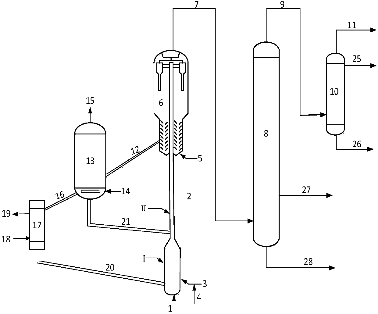
[0082] according to figure 1 The flow of the experiment was carried out, and the shale oil A in Table 1 was used as the raw material for catalytic cracking, and the experiment was carried out on a composite reactor composed of a fluidized bed and a riser. The shale oil A was fed from the bottom, and the bottom of the reactor was fluidized. The diameter of the bed expands into an adsorption zone, and a cold regenerant (the first catalytic cracking catalyst) that takes heat from outside is introduced, while the lower part of the riser reactor is transported into a high-temperature hot regenerant (the second catalytic cracking catalyst), and in the riser reactor , The upper part forms a cracking zone; the CAT-3 catalyst in Table 2 is used, and the heavy oil refining ratio is 0.1. After being preheated at 350°C, shale oil A enters the bottom of the adsorption zone where the diameter of the reactor expands (the inner diameter of the adsorption zone is 3 times the inner diameter of ...

Embodiment 2

[0085] Carry out catalytic cracking according to the method identical with embodiment 1, difference is: introduce the fresh catalyst that exchanges heat with heat regenerative catalytic cracking catalyst as the first catalytic cracking catalyst in the adsorption zone of reactor bottom, operating conditions and product distribution are listed in Table 3.

Embodiment 3

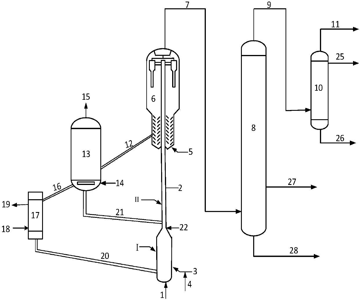
[0093] This example follows figure 2 The process is tested, using shale oil A in Table 1 as the raw material for catalytic cracking, in such as figure 2 The test is carried out on the shown reactor, the shale oil A is fed under, and the diameter of the fluidized bed at the bottom of the reactor is enlarged to be an adsorption zone (the inner diameter of the adsorption zone is 3 times the inner diameter of the cracking zone, and the length of the adsorption zone is 35% of the length of the cracking zone), and introduce a cold regenerant that takes heat from outside, while the lower part of the riser reactor is transported into a high-temperature hot regenerant to form a cracking zone in the upper part of the reactor; using CAT-3 catalyst, the heavy oil is recycled The refining ratio is 0.1. After being preheated at 350°C, shale oil A enters the bottom of the reactor's expanded fluidized bed adsorption zone, and flows upwards with a proper amount of water vapor as the fluidiz...


PUM


Abstract

The invention discloses a fluid catalytic cracking method of shale oil. By introducing a low temperature catalyst, the reactor area is divided into a fluidized bed adsorption area and a riser cracking area. In a non-hydrogen atmosphere, shale oil enters the fluidized bed adsorption area with a lower temperature, impurities such as alkaline nitrides, colloids, heavy metals, and the like are removed through adsorption, then shale oil is introduced into the riser cracking area, and in the riser cracking area, shale oil is contacted with a reclaiming agent with a high temperature and high activity to carry out catalytic cracking reactions. The provided method has the advantages that the shale oil conversion performance is strong, the yield of dry gas and coke is low, and the yield of liquid product is high.

Description

technical field [0001] The present invention relates to the catalytic conversion method of shale oil, more specifically, relates to a kind of method that adopts fluidized bed riser reactor to first absorb and remove the impurity of shale oil and then catalytic cracking, greatly improve the conversion rate of shale oil And reduce the yield of dry gas and coke, so as to realize the method of efficient utilization of shale oil resources. Background technique [0002] Shale oil is the product of thermal decomposition of organic matter after thermal processing of oil shale. It is similar to natural petroleum, but contains more unsaturated hydrocarbons than natural petroleum, and contains non-hydrocarbon organic compounds such as nitrogen, sulfur, and oxygen. . The world's oil shale reserves are equivalent to about 400 billion tons of shale oil, far exceeding the total natural oil reserves; while my country's oil shale resources are very rich, with reserves of about 16 billion to...

Claims


Application Information

Patent Timeline
IPC IPC(8): C10G55/06
Inventor 唐津莲龚剑洪李泽坤
Owner CHINA PETROLEUM & CHEM CORP
Why Eureka
Try Eureka