Method for producing a steel component provided with a metallic coating providing protection against corrosion

A technology for anti-corrosion protection and steel components, applied in the direction of manufacturing tools, heat treatment equipment, process efficiency improvement, etc., can solve the problem that heating will not achieve layer characteristics, and achieve the effect of reducing moisture absorption

Inactive Publication Date: 2016-04-27
THYSSENKRUPP STEEL EURO AG
View PDF5 Cites 6 Cited by
  • Summary
  • Abstract
  • Description
  • Claims
  • Application Information

AI Technical Summary

Problems solved by technology

Consequently, the result is neither uniform heating nor consistent layer properties

Method used

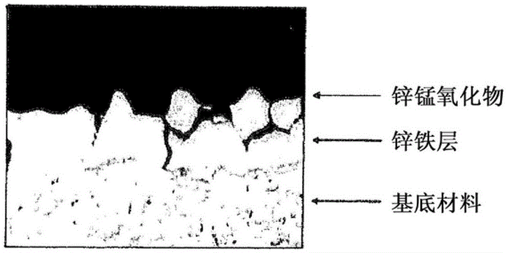
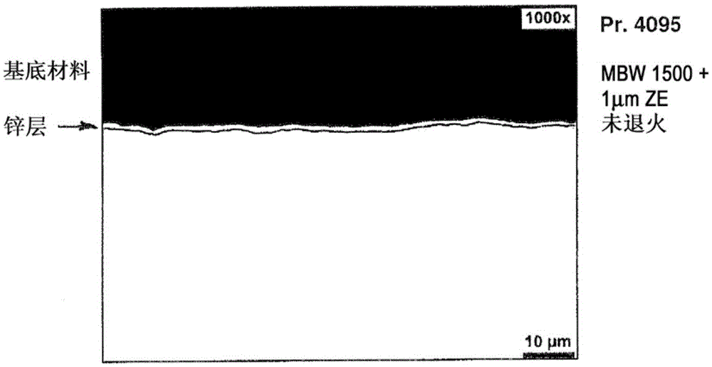
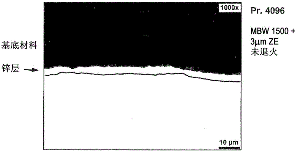

Image

  • Method for producing a steel component provided with a metallic coating providing protection against corrosion
  • Method for producing a steel component provided with a metallic coating providing protection against corrosion
  • Method for producing a steel component provided with a metallic coating providing protection against corrosion

Examples


example 1

[0063] Annealed cold-rolled strips of steel grade 22MnB5 (1.5528) were degreased with alkaline jetting and additionally with electrolyte. The degreasing basin contains a concentration of about 15g / L of a commercially available cleaner with greater than 25% sodium hydroxide, 1-5% fatty alcohol ether, and 5-10% ethoxylated, acrylic acid Oxylated and methylated C12-18 alcohols. The cell temperature was approximately 65°C. The duration of jet degreasing is about 4-6 s. Followed by scrubbing. In the following process, the strips were electrolytically degreased with a residence time of about 3 s through the anode and cathode at a current density of 15 A / dm2. Subsequently, multi-stage rinsing was performed by using a brush with deionized water at room temperature. The duration during flushing is about 2-4s. Then pickling with hydrochloric acid (20 g / L; temperature 35-38° C.) was carried out with a residence time of about 10-12 s. After continuous rinsing by deionized water for ...

example 2

[0073]Hot-rolled strip (pickling) of steel grade 22MnB5 (1.5528) was degreased with alkaline spraying and degreased with electrolyte. The degreasing bath contains a concentration of 20g / L of detergent with greater than 1-5% C12-18 fatty alcohol polyglycol butyl ether and 0.5-2% potassium hydroxide. The cell temperature was approximately 75°C. The duration in the horizontal jet flush is about 10-12 s. Followed by double brushing. In the following process, the strip is electrolytically degreased with a residence time of about 8-10 s through the anode and cathode at a current density of 10 A / dm2. Subsequently, multi-stage rinsing was performed by using a brush with deionized water at room temperature. The duration is about 2-4s. This was followed by a hydrochloric acid pickling (100 g / L; room temperature) with a residence time of about 26-28 s. After combined brushing and fresh water spraying, the plates are transferred after passing through the extrusion device into a horiz...


PUM

PropertyMeasurementUnit
thicknessaaaaaaaaaa

Abstract

The invention provides a method by which a steel component provided with a metallic coating which has good adhesion and provides protection from corrosion can be produced. The problem addressed by the invention is especially that of specifying a corresponding hot forming process which enables a wide range of processing variants. The emphasis here is not on long-lasting corrosion protection but more on high flexibility of the processing properties. For this purpose, a thin zinc layer having a mean layer thickness of less than 5 mum, preferably in the range of 1-4 mum, more preferably in the range of 2-4 mum, is applied by electrolytic means to a flat steel product consisting of a steel material which can be annealed by quenching in a hot forming process and has a yield point of 150-1100 MPa and a tensile strength of 300-1200 MPa. A billet is then obtained from the flat steel product and is heated directly to at least 800 DEG C and then formed to give the steel component, or is first formed to give the steel component which is then heated to at least 800 DEG C. The steel component obtained in each case is subsequently annealed by cooling it with sufficient speed from a sufficiently high temperature.

Description

technical field [0001] The invention relates to a method for producing a steel component provided with a metallic corrosion protection layer by forming a flat steel product of hot press hardenable steel, preferably manganese steel, which is provided with zinc before forming layer. Background technique [0002] When referring to "flat steel products" it is meant steel strips, steel sheets or slabs derived therefrom or the like. [0003] In order to provide the combination of low weight, maximum strength and protection required in modern body construction, thermoformed components from high-strength steels are currently used in areas of these bodies which may be exposed to particularly high loads in the event of a crash. [0004] In the process of hot press hardening (also known as hot forming), steel slabs obtained by splitting cold-rolled or hot-rolled strip are heated to a forming temperature usually above the austenitizing temperature of the various steels and Put it into...

Claims


Application Information

Patent Timeline
Patent Type & Authority Applications(China)
IPC IPC(8): C25D5/02C25D5/48C25D5/50C21D1/18C21D1/42C21D1/673C25D3/22C25D5/36C25D7/06
CPCC25D3/22C25D5/028C25D5/36C25D5/48C25D5/50C21D1/18C25D7/0621C21D1/42C21D1/673C21D8/005C21D1/06C21D1/34C21D1/74C21D6/002C21D6/008C21D8/0205C21D8/0221C21D8/0247C21D9/46C22C38/02C22C38/06C22C38/28Y02P10/25C25D7/00
Inventor 马里亚·科耶尔萨沙·西科拉扬科·巴尼克
Owner THYSSENKRUPP STEEL EURO AG
Why Eureka
Try Eureka